Answered step by step
Verified Expert Solution
Question
1 Approved Answer
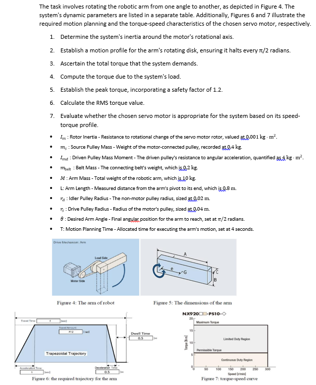
The task involves rotating the robotic arm from one angle to another, as depicted in Figure 4. The system's dynamic parameters are listed in

The task involves rotating the robotic arm from one angle to another, as depicted in Figure 4. The system's dynamic parameters are listed in a separate table. Additionally, Figures 6 and 7 illustrate the required motion planning and the torque-speed characteristics of the chosen servo motor, respectively. 1. Determine the system's inertia around the motor's rotational axis. 2. Establish a motion profile for the arm's rotating disk, ensuring it halts every 1/2 radians. 3. Ascertain the total torque that the system demands. 4. Compute the torque due to the system's load. 5. Establish the peak torque, incorporating a safety factor of 1.2. 6. Calculate the RMS torque value. 7. Evaluate whether the chosen servo motor is appropriate for the system based on its speed- torque profile. . Im: Rotor Inertia - Resistance to rotational change of the servo motor rotor, valued at 0.001 kg - m. m, : Source Pulley Mass - Weight of the motor-connected pulley, recorded at 0.4 kg. Imd: Driven Pulley Mass Moment - The driven pulley's resistance to angular acceleration, quantified 35kg. m. mbelt : Belt Mass - The connecting belt's weight, which is 0,2 kg. M: Arm Mass - Total weight of the robotic arm, which is 10 kg. L: Arm Length - Measured distance from the arm's pivot to its end, which is Q.8 m. * : Idler Pulley Radius - The non-motor pulley radius, sized 3.0.02 m. * : Drive Pulley Radius - Radius of the motor's pulley, sized at 0.04 m. 8: Desired Arm Angle - Final angylar position for the arm to reach, set at /2 radians. T: Motion Planning Time - Allocated time for executing the arm's motion, set at 4 seconds. Drive Mechanism: Arm Load Side QU MoterSide Figure 4: The arm of robot Travel Amount Trapezoidal Trajectory Deceleratie Figure 6: the required trajectory for the arm Dwell Time 0.5 Figure 5: The dimensions of the arm NX920-PS10- Maximum Torque Torque m 15- B 10- Permissible Torque Limited Duty Region Continuous Duty Region 100 150 200 250 Figure 7: torque-speed curve 300
Step by Step Solution
★★★★★
3.52 Rating (159 Votes )
There are 3 Steps involved in it
Step: 1
1 Systems inertia around the motors rotational axis The systems total inertia can be calculated as I...
Get Instant Access to Expert-Tailored Solutions
See step-by-step solutions with expert insights and AI powered tools for academic success
Step: 2

Step: 3

Ace Your Homework with AI
Get the answers you need in no time with our AI-driven, step-by-step assistance
Get Started


