Answered step by step
Verified Expert Solution
Question
1 Approved Answer
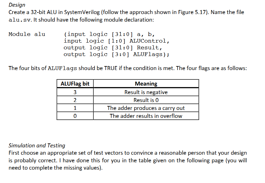
Then create a self-checking testbench for the ALU Design Create a 32-bit ALU in SystemVerilog (follow the approach shown in Figure 5.17). Name the file


Then create a self-checking testbench for the ALU
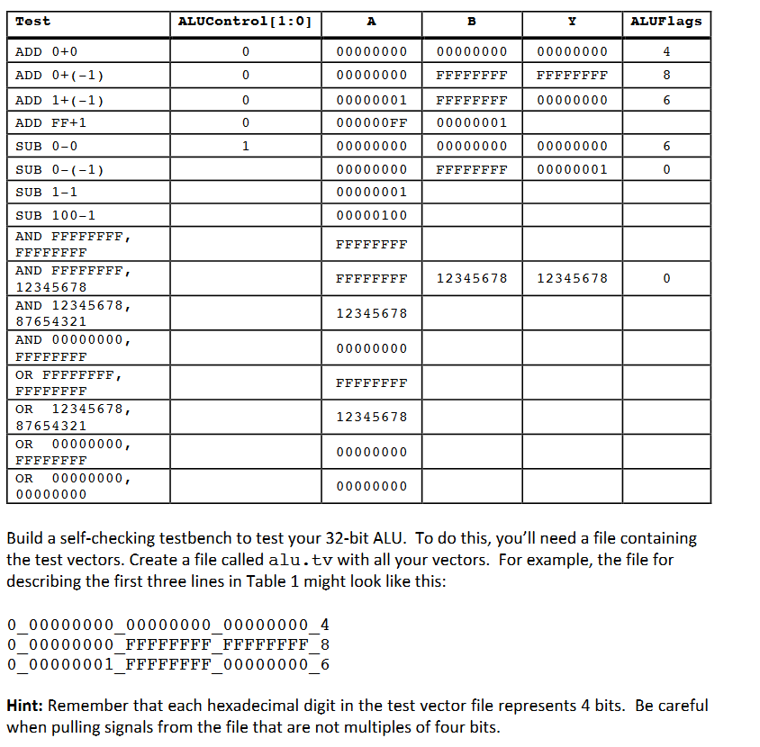
Design Create a 32-bit ALU in SystemVerilog (follow the approach shown in Figure 5.17). Name the file alu. sv. It should have the following module declaration: input logic 131 01 a, b, Module alu input logic 1 01 ALUControl output logic [31:0 Result, output logic 13:01 ALUFlags The four bits of ALUFlags should be TRUE if the condition is met. The four flags are as follows: Meaning ALUFlag bit 3 Result is negative 2 Result is 0 1 The adder produces a carry out 0 The adder results in overflow Simulation and Testing First choose an appropriate set of test vectors to convince a reasonable person that your design is probably correct. have done this for you in the table given on the following page (you will need to complete the missing values)Step by Step Solution
There are 3 Steps involved in it
Step: 1

Get Instant Access to Expert-Tailored Solutions
See step-by-step solutions with expert insights and AI powered tools for academic success
Step: 2

Step: 3

Ace Your Homework with AI
Get the answers you need in no time with our AI-driven, step-by-step assistance
Get Started


