Question: THERMODYNAMICS: Explain the math in the reading and how it relates to calometry in layman terms EXPERIMENTS 6. Heats of Combustion 7. Strain Energy of
THERMODYNAMICS: Explain the math in the reading and how it relates to calometry in layman terms
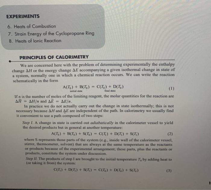
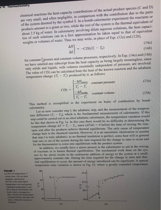
EXPERIMENTS 6. Heats of Combustion 7. Strain Energy of the Cyclopropane Ring 8. Heats of lonic Reaction PRINCIPLES OF CALORIMETRY We are concerned here with the problem of determining experimentally the enthalpy change H or the energy change E accompanying a given isothermal change in state of a system, normally one in which a chemical reaction occurs. We can write the reaction schematically in the form If n is the number of moles of the limiting reagent, the molar quantities for the reaction are H~=H and E=E. In practice we do not actually carry out the change in state isothermally; this is not necessary because H and E are independent of the path. In calorimetry we usually find it convenient to use a path composed of two steps: Step I. A change in state is carried out adiabatically in the calorimeter vessel to yield the desired products but in general at another temperature: A(T0)+B(T0)+S(T0)=C(T1)+D(T1)+S(T1) where S represents those parts of the system (c.g., inside wall of the calorimeter vessel, stirrer, thermometer, solvent) that are always at the same temperature as the reactants or products because of the experimental arrangement; these parts, plus the reactants or products, constitute the system under discussion. Step II. The products of step 1 are brought to the initial temperature T0 by adding heat to (or taking it from) the system: C(Ti)+D(Ti)+S(Ti)=C(T0)+D(T0)+S(T0) As we shall sec, it is often unnecessary to carry out this step in actuality, since the associated change in energy or enthalpy can be calculated from the known temperature difference. By adding Eqs. (2) and (3), we obtain Eq. (1) and verify that these two steps describe a complete path connecting the desired initial and final states. Accordingly, H or E for the change in state (1) is the sum of the values of this quantity pertaining to the two steps: H=H1+HME=E1+Ea The particular convenience of the path described is that the heat q for step I is zero, while the heq g for step Il can be either measured or calculated. It can be measured direetly by carrying oit step II (or its inverse) through the addition to the system of a measurable quantity of heat or electrical energy, or it can be calculated from the temperature change (T1T0) resulting from adiabatic step l if the heat capacity of the product system is known. For step I, H1=qr=0E1=qr=0constantpressureconstantvolume (5a) Thus, if both steps are carried out at constant pressure, H=Hu and if both are carried out at constant volume, E=Eu Whether the process is carried out at constant pressure or at constant volume is a matter of convenience. In nearly all caves it is most convenient to carry it out at constant pressure; the experiment on heats of ionic reaction is an example. An exception to the general rule is the determination of a heat of combustion, which is conveniently carried out at constant volume in a "bomb calorimeter." However, we can easily calculate / from E as determined from a constant-volume process (or E from H as determined from a constantpressure process) by use of the equation H=F+(pV) When all reactants and products are condensed phases, the M(pl) term is aegligible in comparison with H or E, and the distinction between these two quantities is unimportant. When gases are involved, as in the case of combustion, the (p) term is likely to be significant in magnitude, though still small in comparison with H or E. Since it is small, we can employ the perfect-gas law and rewrite Eq (7) in the form H=E+RTnre where ng is the increase in the number of moles of gas in the syatcm. We nust now concem cumelves with proeedores for determining M/ or AK for step 11. We might ewvisge mep II being carried out by adling heat to the sy werrt or taking beat away from the system and messuring q for thin procesi + Usally, however, it is much easier to measure work than lieat, In particular, elocticel woek done on the systean by a beating coil (often refered to as Jowite hnouting) ean be used coaveniently to carry out either step II or its inverse, whichever is endothermic. Since the work is dissipated inside the system, the work is positive: wil=VhdQ=Vhldt where Vh is the voltage drop across the heater, Q is the electric charge, and I is the electric current. For precise work, one should measure both Vk and I during the heating period. In many instances, however, it is possible to assume that the resistance of the heating coil Rh is constant and make only measurements of I by determining the potential drop V4 across a standard resistance Ri in series with the heating coil. In such a case, one can write wd=I2Rhdt=Rt2RbVs2dt Note that the electrical work given by Eq. (9) is in joules when resistance is in ohms, potential (voltage) is in volts, and time is in seconds. If the electrical heafing is done adiabatically, HI=waconstantpressureEn=wdconstantvolume (10a) Our discussion so for has been limited to determining Ha or Ea by directly carrying out step II (or its inverse). However, it is often not necessary to carry out this step in actuality. If we know or can determine the heat capacity of the system, the temperature change (T1T0) resulting from step I provides all the additional information we need: HB=TiTpCp(C+D+S)dTEu=riTpCv(C+D+S)dT The heat eapacities ordinarily vary only slightly over the small temperarure ranges involved: accordingly we can simplify Eqs. (11) and combine them with Eqx. (6) to obtain the fumiliar expressions HE=Cp(C+D+S)(T1T0)=C0(C+D+S)(T1T0) Where C,, and Cv are average values over the iemperuture nange. The heat eapacity must be determined if it is not known. A diret method, which depends on the ansumption of the constancy of heat capacities over a mall nupee of temperauire, is to measure the adiabatic temperature rise (T2T1) producod by the divipation of a meaturnd quantiyy of electrical energy. We then obtain c2ci}=x2x13Wa1 at conatar premure or at consaan volume, meypectively. This methad is ctemplifitad in the oxperimen on beate of ianic tration. An indirest methnd of determining the beat capociby a bor canry ont anoder noction altopether, for whith thic heat of raetion is inown in be ame calkeimeter inder the same chemical reactions the heat-capacity contributions of the actual product species ( C and D) are very small, and often negligible, in comparison with the contribution due to the parts of the system denoted by the symbol S. In a bomb-calorimeter experiment the reactants or products amount to a gram or two, while the rest of the system is the thermal equivalent of about 2.5kg of water. In calorimetry involving dilute aqueous solutions, the heat capacities of such solutions can in a first approximation be taken equal to that of equivalent weights or volumes of water. Thus we may write, in place of Eqs. (12a) and (12b), HE}=C(S)(TtT0) we have omitted any subseript from the heit ce only solids and liquids, with volumes essentially independent of pressure, are involved. C(S)={T2T1HlamnT2T1Eiwmconstantpressureconstantvolume This method is exemplified in the experiment on heats of combustion by bomb calorimetry. Let us now consider step 1, the adiabatic step, and the measurement of the tempenture difference (T1T0), which is the fundamental measurement of calorimetry. If this step could be carried out in an ideal adiabatic calorimeter, the temperature variation would be tike that shown in Fig. la. In this case there would be no difficulty in determining the temperature change T=T1T0, since (dTldt)=0 before the time of mixing the reactants and affer the products achieve thermal equilibrium. The only cause of temperature change bere is the chemical reaction. However, it is an unrealistic idealization to assume that step l is truly adiabatic; as no thermal insulation is perfect, wome heat will in general leak into or out of the system during the time requirad for the change in state to occur and for the thermometer to come into equilibrium with the product system. In addition, we usually have a stirner present in the calorimeter to aid in the mixing of reactants or to hasten thermal equilibration. The mechanical work done on the system by the stimer resuls in the continuous addition of enery to the system at a small, appeosimately constant rate. During the time required for the change in state and thermal equilibration to occur, the amount of energy introtused can be significant. A typical tempenture time variation is shown in Fie 16, where a greatly expanded temperature noune 1 in) Par if ienepediue T veruie lime thor art beal Di Piat wata inernupteit lesera puet wais and wiekth cale has been used with an internupted temperature axis in order to show clearly the preand postreaction temperature changes, in this case, a more detailed analysis is needed in order to extract the adiabatic T value from the observed data points. Consider Fig. 2, which shows a schematic plot of T(t) associated with step I as carried out in a typical calorimeter. This plot is based on the assumptions that the heat leakage through the calorimeter walls is small and the energy input due to the stirrer is moderate. These assumptions are appropriate for the thermochemistry experiments deseribed in this book. The initial temperature Ti is conveniently taken to be the value at time ti when the reaction is initiated following a period of essentially linear T.t readings that serve to establish the initial (prereaction) drift rate (dTid). . The temperature is followed after reaction for a period long enough to achieve a roughly linear variation and to establish the drift rate (dT/dt)f at an arbitrary point Tf, if The analysis of step I will be given for a constant-volume calorimeter run, but analogous results hold at constant pressure. The effeet of heat leakage is evaluated using Newton's law of cooling. dtdq=k(TTi) a thermal rate constant that depends on the thermal conductivity of the calorimeter insulation. The mechanical power input to the system (dwidn) will be denoted by P, which is assumed to be a constant independent of t. Thus CvdtdT=dtdE=Pk(TTv) or (dtdT)matria=C1[Pk(TTj)] temperature difference TfTi shown in Fig.2 is given by TfTi=T+4t(dtdT)mattatdt Whero T=T1Tn is the change due to an adiabatic chemical reaction and the iategnal is: the net diange due so beat lenk and stirrer power input. Thus it follows that T1Ti=T=(TfTi)C1t(P24T(t)Ti)dt Ficurs 2 The following are the most important experimental approaches aimed at minimizing the effect of nonadiabatic conditions and the effect of the stirrer; they can be used separately or in combination. 1. The calorimeter may be built in such a way as to minimize heat conduction into or out of the system. A vessel with an evacuated jacket (Dewar flask), often with silvered surfaces to minimize the effect of heat radiation, may be used. This corresponds to making the thermal rate constant k very small. 2. One may interpose between system and surroundings an "adiabatic jacket," reasonably well insulated from both. This jacket is so constructed that its temperature can be adjusted at will from outside, as, for example, by supplying electrical energy to a heating circuit. In use, the temperature of the jacket is continuously adjusted so as to be as close as possible to that of the system, so that no significant quuntity of heat will tend to flow between the system and the jacket. This corresponds to making TT, very small. 3. The stirring system may be carefully designed to produce the least rate of work consistent with the requirement of thorough and reasonably rapid mixing. This corresponds to making P small. 4. We may assume that the rate of gain or loss of energy by the system resulting from heat leakage and stirrer work is reasonably constant with time at any given temperature. We may therefore assume that the temperature variation as a function of time should be initially and finally almost linear. One simple possibility would be k(TTi)=0 and P= constant, in which case (dT/l)= P/C has the same value at all tt and Eq. (19) gives T=TfTfdtdT(tftf)ifk(TTf)=0 As shown in Fig. 3a,T in this case is just the vertical distance between two parallel T=t lines. Naturally, this distance can be evaluated at any L. A more realistic possibility is that k(TT) is amall but not negligible and P= constunt. In this case the Tt plot looks like Fig 3b, where the initial leak + stir drift nte (dT7dt) at t, differs from the final rate (dT/dt)f at if. Ht can be shown' in this ease that T is given by T=(TfTi)(dtdT)(Litf)(dtdT))t(tftd) where td is chosen so that the two shaded regions in Fig. 3b are of equal area. The derivation of Eq. (22) from Eq. (20) requires a bit of sleight-of-hand manipulation. Let us define a new variable TcTs+(P/k), in terms of which Eq. (18) gives (dtdT)f=Ck(TiTc)and(dtdT)f=Ck(TfTc) and Eq. (20) becomes T=(TfTi)+Cktf(TTc)dt Note that cct1(TTc)dt=ctc(TTi)dt+(TiTc)(tdti)+cctf(TTf)dt+(TfTc)(tftd) By the definition given above for t, the two integrals in Eq. (25) cancel out. Substituting Eq. (25) into Eq. (24) and making use of Eq. (23) leads direetly to Eq. (22). It is clear from this derivation that Eq. (22) will be valid even if the T variation prior to t1 and after tf is not linear. In such a case, one merely uses the tangent to the Tt curves at Ti and t.. In summary, one should follow the temperature variation before and after reaction for a period long enough to allow a good evaluation of (dT/dt), and (dT/dt). Then make a plot like Fig. 3b, choose the point (T,tj, determine the best value for tb, and calculate T from Eq. (22). In practice tf should be chosen as close to ti as is consistent with a wellcharacterized final drif rate, Note that t, will lie much closer to t; than to t, for reactions that go to completion quickly. Whenever the time required for a change in state is long, as in the case of determining the heat capacity by clectrical beating, the position of t will lie near the middle of the range t; to t, As an approximate procedure for handling the analysis of electrical heating plots, one can choose tis as the time the heater is turned on and tf as the time it is tumed off and choose t as the midpoint of this heating period. In the experiments on heats of combastion, we make use of approaches 2 (optionally), 3, and 4. In the experiment on heats of ionic reaction, we make use of 1,3 , and 4 , In all cases the small temperature chunges can be measured with adequate precision with a usine a inexpensive mercury thermometer. Alierautively the measurements can be made computer Calitration of the Chemapter XVII, which can be monitored repetitively by a this case, bua this prope tue thermels istor for improved linearity and accuracy is needed in computer io a meaburement device. EXPERIMENTS 6. Heats of Combustion 7. Strain Energy of the Cyclopropane Ring 8. Heats of lonic Reaction PRINCIPLES OF CALORIMETRY We are concerned here with the problem of determining experimentally the enthalpy change H or the energy change E accompanying a given isothermal change in state of a system, normally one in which a chemical reaction occurs. We can write the reaction schematically in the form If n is the number of moles of the limiting reagent, the molar quantities for the reaction are H~=H and E=E. In practice we do not actually carry out the change in state isothermally; this is not necessary because H and E are independent of the path. In calorimetry we usually find it convenient to use a path composed of two steps: Step I. A change in state is carried out adiabatically in the calorimeter vessel to yield the desired products but in general at another temperature: A(T0)+B(T0)+S(T0)=C(T1)+D(T1)+S(T1) where S represents those parts of the system (c.g., inside wall of the calorimeter vessel, stirrer, thermometer, solvent) that are always at the same temperature as the reactants or products because of the experimental arrangement; these parts, plus the reactants or products, constitute the system under discussion. Step II. The products of step 1 are brought to the initial temperature T0 by adding heat to (or taking it from) the system: C(Ti)+D(Ti)+S(Ti)=C(T0)+D(T0)+S(T0) As we shall sec, it is often unnecessary to carry out this step in actuality, since the associated change in energy or enthalpy can be calculated from the known temperature difference. By adding Eqs. (2) and (3), we obtain Eq. (1) and verify that these two steps describe a complete path connecting the desired initial and final states. Accordingly, H or E for the change in state (1) is the sum of the values of this quantity pertaining to the two steps: H=H1+HME=E1+Ea The particular convenience of the path described is that the heat q for step I is zero, while the heq g for step Il can be either measured or calculated. It can be measured direetly by carrying oit step II (or its inverse) through the addition to the system of a measurable quantity of heat or electrical energy, or it can be calculated from the temperature change (T1T0) resulting from adiabatic step l if the heat capacity of the product system is known. For step I, H1=qr=0E1=qr=0constantpressureconstantvolume (5a) Thus, if both steps are carried out at constant pressure, H=Hu and if both are carried out at constant volume, E=Eu Whether the process is carried out at constant pressure or at constant volume is a matter of convenience. In nearly all caves it is most convenient to carry it out at constant pressure; the experiment on heats of ionic reaction is an example. An exception to the general rule is the determination of a heat of combustion, which is conveniently carried out at constant volume in a "bomb calorimeter." However, we can easily calculate / from E as determined from a constant-volume process (or E from H as determined from a constantpressure process) by use of the equation H=F+(pV) When all reactants and products are condensed phases, the M(pl) term is aegligible in comparison with H or E, and the distinction between these two quantities is unimportant. When gases are involved, as in the case of combustion, the (p) term is likely to be significant in magnitude, though still small in comparison with H or E. Since it is small, we can employ the perfect-gas law and rewrite Eq (7) in the form H=E+RTnre where ng is the increase in the number of moles of gas in the syatcm. We nust now concem cumelves with proeedores for determining M/ or AK for step 11. We might ewvisge mep II being carried out by adling heat to the sy werrt or taking beat away from the system and messuring q for thin procesi + Usally, however, it is much easier to measure work than lieat, In particular, elocticel woek done on the systean by a beating coil (often refered to as Jowite hnouting) ean be used coaveniently to carry out either step II or its inverse, whichever is endothermic. Since the work is dissipated inside the system, the work is positive: wil=VhdQ=Vhldt where Vh is the voltage drop across the heater, Q is the electric charge, and I is the electric current. For precise work, one should measure both Vk and I during the heating period. In many instances, however, it is possible to assume that the resistance of the heating coil Rh is constant and make only measurements of I by determining the potential drop V4 across a standard resistance Ri in series with the heating coil. In such a case, one can write wd=I2Rhdt=Rt2RbVs2dt Note that the electrical work given by Eq. (9) is in joules when resistance is in ohms, potential (voltage) is in volts, and time is in seconds. If the electrical heafing is done adiabatically, HI=waconstantpressureEn=wdconstantvolume (10a) Our discussion so for has been limited to determining Ha or Ea by directly carrying out step II (or its inverse). However, it is often not necessary to carry out this step in actuality. If we know or can determine the heat capacity of the system, the temperature change (T1T0) resulting from step I provides all the additional information we need: HB=TiTpCp(C+D+S)dTEu=riTpCv(C+D+S)dT The heat eapacities ordinarily vary only slightly over the small temperarure ranges involved: accordingly we can simplify Eqs. (11) and combine them with Eqx. (6) to obtain the fumiliar expressions HE=Cp(C+D+S)(T1T0)=C0(C+D+S)(T1T0) Where C,, and Cv are average values over the iemperuture nange. The heat eapacity must be determined if it is not known. A diret method, which depends on the ansumption of the constancy of heat capacities over a mall nupee of temperauire, is to measure the adiabatic temperature rise (T2T1) producod by the divipation of a meaturnd quantiyy of electrical energy. We then obtain c2ci}=x2x13Wa1 at conatar premure or at consaan volume, meypectively. This methad is ctemplifitad in the oxperimen on beate of ianic tration. An indirest methnd of determining the beat capociby a bor canry ont anoder noction altopether, for whith thic heat of raetion is inown in be ame calkeimeter inder the same chemical reactions the heat-capacity contributions of the actual product species ( C and D) are very small, and often negligible, in comparison with the contribution due to the parts of the system denoted by the symbol S. In a bomb-calorimeter experiment the reactants or products amount to a gram or two, while the rest of the system is the thermal equivalent of about 2.5kg of water. In calorimetry involving dilute aqueous solutions, the heat capacities of such solutions can in a first approximation be taken equal to that of equivalent weights or volumes of water. Thus we may write, in place of Eqs. (12a) and (12b), HE}=C(S)(TtT0) we have omitted any subseript from the heit ce only solids and liquids, with volumes essentially independent of pressure, are involved. C(S)={T2T1HlamnT2T1Eiwmconstantpressureconstantvolume This method is exemplified in the experiment on heats of combustion by bomb calorimetry. Let us now consider step 1, the adiabatic step, and the measurement of the tempenture difference (T1T0), which is the fundamental measurement of calorimetry. If this step could be carried out in an ideal adiabatic calorimeter, the temperature variation would be tike that shown in Fig. la. In this case there would be no difficulty in determining the temperature change T=T1T0, since (dTldt)=0 before the time of mixing the reactants and affer the products achieve thermal equilibrium. The only cause of temperature change bere is the chemical reaction. However, it is an unrealistic idealization to assume that step l is truly adiabatic; as no thermal insulation is perfect, wome heat will in general leak into or out of the system during the time requirad for the change in state to occur and for the thermometer to come into equilibrium with the product system. In addition, we usually have a stirner present in the calorimeter to aid in the mixing of reactants or to hasten thermal equilibration. The mechanical work done on the system by the stimer resuls in the continuous addition of enery to the system at a small, appeosimately constant rate. During the time required for the change in state and thermal equilibration to occur, the amount of energy introtused can be significant. A typical tempenture time variation is shown in Fie 16, where a greatly expanded temperature noune 1 in) Par if ienepediue T veruie lime thor art beal Di Piat wata inernupteit lesera puet wais and wiekth cale has been used with an internupted temperature axis in order to show clearly the preand postreaction temperature changes, in this case, a more detailed analysis is needed in order to extract the adiabatic T value from the observed data points. Consider Fig. 2, which shows a schematic plot of T(t) associated with step I as carried out in a typical calorimeter. This plot is based on the assumptions that the heat leakage through the calorimeter walls is small and the energy input due to the stirrer is moderate. These assumptions are appropriate for the thermochemistry experiments deseribed in this book. The initial temperature Ti is conveniently taken to be the value at time ti when the reaction is initiated following a period of essentially linear T.t readings that serve to establish the initial (prereaction) drift rate (dTid). . The temperature is followed after reaction for a period long enough to achieve a roughly linear variation and to establish the drift rate (dT/dt)f at an arbitrary point Tf, if The analysis of step I will be given for a constant-volume calorimeter run, but analogous results hold at constant pressure. The effeet of heat leakage is evaluated using Newton's law of cooling. dtdq=k(TTi) a thermal rate constant that depends on the thermal conductivity of the calorimeter insulation. The mechanical power input to the system (dwidn) will be denoted by P, which is assumed to be a constant independent of t. Thus CvdtdT=dtdE=Pk(TTv) or (dtdT)matria=C1[Pk(TTj)] temperature difference TfTi shown in Fig.2 is given by TfTi=T+4t(dtdT)mattatdt Whero T=T1Tn is the change due to an adiabatic chemical reaction and the iategnal is: the net diange due so beat lenk and stirrer power input. Thus it follows that T1Ti=T=(TfTi)C1t(P24T(t)Ti)dt Ficurs 2 The following are the most important experimental approaches aimed at minimizing the effect of nonadiabatic conditions and the effect of the stirrer; they can be used separately or in combination. 1. The calorimeter may be built in such a way as to minimize heat conduction into or out of the system. A vessel with an evacuated jacket (Dewar flask), often with silvered surfaces to minimize the effect of heat radiation, may be used. This corresponds to making the thermal rate constant k very small. 2. One may interpose between system and surroundings an "adiabatic jacket," reasonably well insulated from both. This jacket is so constructed that its temperature can be adjusted at will from outside, as, for example, by supplying electrical energy to a heating circuit. In use, the temperature of the jacket is continuously adjusted so as to be as close as possible to that of the system, so that no significant quuntity of heat will tend to flow between the system and the jacket. This corresponds to making TT, very small. 3. The stirring system may be carefully designed to produce the least rate of work consistent with the requirement of thorough and reasonably rapid mixing. This corresponds to making P small. 4. We may assume that the rate of gain or loss of energy by the system resulting from heat leakage and stirrer work is reasonably constant with time at any given temperature. We may therefore assume that the temperature variation as a function of time should be initially and finally almost linear. One simple possibility would be k(TTi)=0 and P= constant, in which case (dT/l)= P/C has the same value at all tt and Eq. (19) gives T=TfTfdtdT(tftf)ifk(TTf)=0 As shown in Fig. 3a,T in this case is just the vertical distance between two parallel T=t lines. Naturally, this distance can be evaluated at any L. A more realistic possibility is that k(TT) is amall but not negligible and P= constunt. In this case the Tt plot looks like Fig 3b, where the initial leak + stir drift nte (dT7dt) at t, differs from the final rate (dT/dt)f at if. Ht can be shown' in this ease that T is given by T=(TfTi)(dtdT)(Litf)(dtdT))t(tftd) where td is chosen so that the two shaded regions in Fig. 3b are of equal area. The derivation of Eq. (22) from Eq. (20) requires a bit of sleight-of-hand manipulation. Let us define a new variable TcTs+(P/k), in terms of which Eq. (18) gives (dtdT)f=Ck(TiTc)and(dtdT)f=Ck(TfTc) and Eq. (20) becomes T=(TfTi)+Cktf(TTc)dt Note that cct1(TTc)dt=ctc(TTi)dt+(TiTc)(tdti)+cctf(TTf)dt+(TfTc)(tftd) By the definition given above for t, the two integrals in Eq. (25) cancel out. Substituting Eq. (25) into Eq. (24) and making use of Eq. (23) leads direetly to Eq. (22). It is clear from this derivation that Eq. (22) will be valid even if the T variation prior to t1 and after tf is not linear. In such a case, one merely uses the tangent to the Tt curves at Ti and t.. In summary, one should follow the temperature variation before and after reaction for a period long enough to allow a good evaluation of (dT/dt), and (dT/dt). Then make a plot like Fig. 3b, choose the point (T,tj, determine the best value for tb, and calculate T from Eq. (22). In practice tf should be chosen as close to ti as is consistent with a wellcharacterized final drif rate, Note that t, will lie much closer to t; than to t, for reactions that go to completion quickly. Whenever the time required for a change in state is long, as in the case of determining the heat capacity by clectrical beating, the position of t will lie near the middle of the range t; to t, As an approximate procedure for handling the analysis of electrical heating plots, one can choose tis as the time the heater is turned on and tf as the time it is tumed off and choose t as the midpoint of this heating period. In the experiments on heats of combastion, we make use of approaches 2 (optionally), 3, and 4. In the experiment on heats of ionic reaction, we make use of 1,3 , and 4 , In all cases the small temperature chunges can be measured with adequate precision with a usine a inexpensive mercury thermometer. Alierautively the measurements can be made computer Calitration of the Chemapter XVII, which can be monitored repetitively by a this case, bua this prope tue thermels istor for improved linearity and accuracy is needed in computer io a meaburement device