Answered step by step
Verified Expert Solution
Question
1 Approved Answer
This is a problem statement . Need the MATLAB code for all the specifications ( specify with number of question to which the code is
This is a problem statement . Need the MATLAB code for all the specifications ( specify with number of question to which the code is written ) and comments please .Need as soon as possible . 

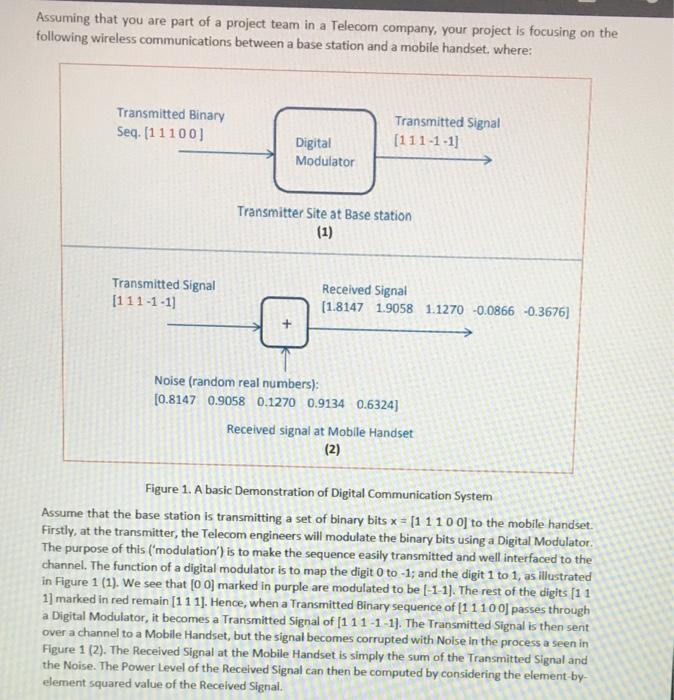
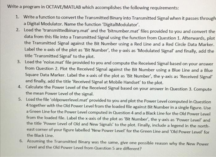
Assuming that you are part of a project team in a Telecom company, your project is focusing on the following wireless communications between a base station and a mobile handset, where: Transmitted Binary Seq. (1 1100) Transmitted Signal (111-1-1] Digital Modulator Transmitter Site at Base station (1) Transmitted Signal [111-1-1) Received Signal (1.8147 1.9058 1.1270 -0.0866 -0.3676) Noise (random real numbers): (0.8147 0.9058 0.1270 0.9134 0.6324] Received signal at Mobile Handset (2) Figure 1. A basic Demonstration of Digital Communication System Assume that the base station is transmitting a set of binary bits x = (1 11 0 0 to the mobile handset. Firstly, at the transmitter, the Telecom engineers will modulate the binary bits using a Digital Modulator. The purpose of this ("modulation') is to make the sequence easily transmitted and well interfaced to the channel. The function of a digital modulator is to map the digit 0 to -1; and the digit 1 to 1, as illustrated in Figure 1 (1). We see that (O O marked in purple are modulated to be [-1-1). The rest of the digits (11 1] marked in red remain [111]. Hence, when a Transmitted Binary sequence of [11100 passes through a Digital Modulator, it becomes a Transmitted Signal of [111-1-1]. The Transmitted Signal is then senit over a channel to a Mobile Handset, but the signal becomes corrupted with Noise in the process a seen in Figure 1 (2). The Received Signal at the Mobile Handset is simply the sum of the Transmitted Signal and the Noise. The Power Level of the Received Signal can then be computed by considering the element-by- element squared value of the Received Signal. Write a program in OCTAVE/MATLAB which accomplishes the following requirements: 1. Write a function to convert the Transmitted Binary into Transmitted Signal when it passes through a Digital Modulator. Name the function 'Digital Modulator. 2. Load the 'transmittedbinary.mat' and the 'bitnumber.mat' files provided to you and convert the data from this file into a Transmitted Signal using the function from Question 1. Afterwards, plot the Transmitted Signal against the Bit Number using a Red Line and a Red Circle Data Marker. Label the x-axis of the plot as 'Bit Number', the y-axis as 'Modulated Signal and finally, add the title Transmitted Signal to the plot. 3. Load the 'noise.mat' file provided to you and compute the Received Signal based on your answer from Question 2. Plot the Received Signal against the Bit Number using a Blue Line and a Blue Square Data Marker. Label the x-axis of the plot as 'Bit Number', the y-axis as 'Received Signal and finally, add the title 'Received Signal at Mobile Handset to the plot. 4. Calculate the Power Level of the Received Signal based on your answer in Question 3. Compute the mean Power Level of the signal. 5. Load the file 'oldpowerlevel.mat provided to you and plot the Power Level computed in Question 4 together with the Old Power Level from the loaded file against Bit Number in a single figure. Use a Green Line for the Power Level computed in Question 4 and a Black Line for the Old Power Level from the loaded file. Label the x-axis of the plot as 'Bit Number', the y-axis as 'Power Level and the title 'Power Level of Old and New Signals' to the plot. Finally, include a legend in the north- east corner of your figure labelled 'New Power Level for the Green Line and 'Old Power Level for the Black Line. 6. Assuming the Transmitted Binary was the same, give one possible reason why the New Power Level and the Old Power Level from Question 5 are different? Assuming that you are part of a project team in a Telecom company, your project is focusing on the following wireless communications between a base station and a mobile handset, where: Transmitted Binary Seq. (1 1100) Transmitted Signal (111-1-1] Digital Modulator Transmitter Site at Base station (1) Transmitted Signal [111-1-1) Received Signal (1.8147 1.9058 1.1270 -0.0866 -0.3676) Noise (random real numbers): (0.8147 0.9058 0.1270 0.9134 0.6324] Received signal at Mobile Handset (2) Figure 1. A basic Demonstration of Digital Communication System Assume that the base station is transmitting a set of binary bits x = (1 11 0 0 to the mobile handset. Firstly, at the transmitter, the Telecom engineers will modulate the binary bits using a Digital Modulator. The purpose of this ("modulation') is to make the sequence easily transmitted and well interfaced to the channel. The function of a digital modulator is to map the digit 0 to -1; and the digit 1 to 1, as illustrated in Figure 1 (1). We see that (O O marked in purple are modulated to be [-1-1). The rest of the digits (11 1] marked in red remain [111]. Hence, when a Transmitted Binary sequence of [11100 passes through a Digital Modulator, it becomes a Transmitted Signal of [111-1-1]. The Transmitted Signal is then senit over a channel to a Mobile Handset, but the signal becomes corrupted with Noise in the process a seen in Figure 1 (2). The Received Signal at the Mobile Handset is simply the sum of the Transmitted Signal and the Noise. The Power Level of the Received Signal can then be computed by considering the element-by- element squared value of the Received Signal. Write a program in OCTAVE/MATLAB which accomplishes the following requirements: 1. Write a function to convert the Transmitted Binary into Transmitted Signal when it passes through a Digital Modulator. Name the function 'Digital Modulator. 2. Load the 'transmittedbinary.mat' and the 'bitnumber.mat' files provided to you and convert the data from this file into a Transmitted Signal using the function from Question 1. Afterwards, plot the Transmitted Signal against the Bit Number using a Red Line and a Red Circle Data Marker. Label the x-axis of the plot as 'Bit Number', the y-axis as 'Modulated Signal and finally, add the title Transmitted Signal to the plot. 3. Load the 'noise.mat' file provided to you and compute the Received Signal based on your answer from Question 2. Plot the Received Signal against the Bit Number using a Blue Line and a Blue Square Data Marker. Label the x-axis of the plot as 'Bit Number', the y-axis as 'Received Signal and finally, add the title 'Received Signal at Mobile Handset to the plot. 4. Calculate the Power Level of the Received Signal based on your answer in Question 3. Compute the mean Power Level of the signal. 5. Load the file 'oldpowerlevel.mat provided to you and plot the Power Level computed in Question 4 together with the Old Power Level from the loaded file against Bit Number in a single figure. Use a Green Line for the Power Level computed in Question 4 and a Black Line for the Old Power Level from the loaded file. Label the x-axis of the plot as 'Bit Number', the y-axis as 'Power Level and the title 'Power Level of Old and New Signals' to the plot. Finally, include a legend in the north- east corner of your figure labelled 'New Power Level for the Green Line and 'Old Power Level for the Black Line. 6. Assuming the Transmitted Binary was the same, give one possible reason why the New Power Level and the Old Power Level from Question 5 are different 

Step by Step Solution
There are 3 Steps involved in it
Step: 1

Get Instant Access to Expert-Tailored Solutions
See step-by-step solutions with expert insights and AI powered tools for academic success
Step: 2

Step: 3

Ace Your Homework with AI
Get the answers you need in no time with our AI-driven, step-by-step assistance
Get Started


