This is a question for the class formal language with applications, please read the whole thing before answering and complete all the requirements of the question. I posted this same question yesterday and didn't get a satisfactory answer.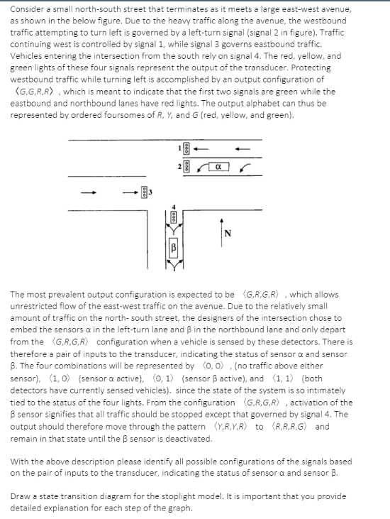
Consider a small north-south street that terminates as it meets a large east-west avenue, as shown in the below figure. Due to the heavy traffic along the avenue, the westbound traffic attempting to turn left is governed by a left-turn signal (signal 2 in figure). Traffic continuing west is controlled by signal 1, while signal 3 governs eastbound traffic. Vehicles entering the intersection from the south rely on signal 4. The red, yellow, and green lights of these four signals represent the output of the transducer. Protecting westbound traffic while turning left is accomplished by an output configuration of (G,GR,R), which is meant to indicate that the first two signals are green while the eastbound and northbound lanes have red lights. The output alphabet can thus be represented by ordered foursomes of R, Y, and G(red, yellow, and green). 000000 a The most prevalent output configuration is expected to be (GR.GR), which allows unrestricted flow of the east-west traffic on the avenue. Due to the relatively small amount of traffic on the north-south street, the designers of the intersection chose to embed the sensors a in the left-turn lane and B in the northbound lane and only depart from the (GR.GR) configuration when a vehicle is sensed by these detectors. There is therefore a pair of inputs to the transducer, indicating the status of sensor a and sensor B. The four combinations will be represented by (0,0), (no traffic above either sensor), (1, 0) (sensor a active), (0, 1) (sensor Bactive), and (1, 1) (both detectors have currently sensed vehicles). since the state of the system is so intimately tied to the status of the four lights. From the configuration G,R,GR), activation of the B sensor signifies that all traffic should be stopped except that governed by signal 4. The output should therefore move through the pattern (Y,RY,R) to (R.R.R.G) and remain in that state until the B sensor is deactivated. With the above description please identify all possible configurations of the signals based on the pair of inputs to the transducer, indicating the status of sensor a and sensor B. Draw a state transition diagram for the stoplight model. It is important that you provide detailed explanation for each step of the graph. Consider a small north-south street that terminates as it meets a large east-west avenue, as shown in the below figure. Due to the heavy traffic along the avenue, the westbound traffic attempting to turn left is governed by a left-turn signal (signal 2 in figure). Traffic continuing west is controlled by signal 1, while signal 3 governs eastbound traffic. Vehicles entering the intersection from the south rely on signal 4. The red, yellow, and green lights of these four signals represent the output of the transducer. Protecting westbound traffic while turning left is accomplished by an output configuration of (G,GR,R), which is meant to indicate that the first two signals are green while the eastbound and northbound lanes have red lights. The output alphabet can thus be represented by ordered foursomes of R, Y, and G(red, yellow, and green). 000000 a The most prevalent output configuration is expected to be (GR.GR), which allows unrestricted flow of the east-west traffic on the avenue. Due to the relatively small amount of traffic on the north-south street, the designers of the intersection chose to embed the sensors a in the left-turn lane and B in the northbound lane and only depart from the (GR.GR) configuration when a vehicle is sensed by these detectors. There is therefore a pair of inputs to the transducer, indicating the status of sensor a and sensor B. The four combinations will be represented by (0,0), (no traffic above either sensor), (1, 0) (sensor a active), (0, 1) (sensor Bactive), and (1, 1) (both detectors have currently sensed vehicles). since the state of the system is so intimately tied to the status of the four lights. From the configuration G,R,GR), activation of the B sensor signifies that all traffic should be stopped except that governed by signal 4. The output should therefore move through the pattern (Y,RY,R) to (R.R.R.G) and remain in that state until the B sensor is deactivated. With the above description please identify all possible configurations of the signals based on the pair of inputs to the transducer, indicating the status of sensor a and sensor B. Draw a state transition diagram for the stoplight model. It is important that you provide detailed explanation for each step of the graph