

Answered step by step
Verified Expert Solution
Question
1 Approved Answer
This is a question from refrigeration, please pick it up only if you are going to answer fully. Thank you. Q1 As schematically shown in
This is a question from refrigeration, please pick it up only if you are going to answer fully. Thank you.
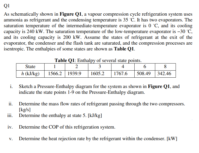
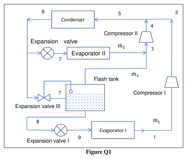
Q1 As schematically shown in Figure Q1, a vapour compression cycle refrigeration system uses ammonia as refrigerant and the condensing temperature is 35 C. It has two evaporators. The saturation temperature of the intermediate-temperature evaporator is 0 C, and its cooling capacity is 240 kW. The saturation temperature of the low-temperature evaporator is 30 C, and its cooling capacity is 200 kW. Assume the states of refrigerant at the exit of the evaporator, the condenser and the flash tank are saturated, and the compression processes are isentropic. The enthalpies of some states are shown as Table Q1. State h (kJ/kg) 1. Table Q1: Enthalpy of several state points. 1 2 3 4 6 1566.2 1939.9 1605.2 1767.6 508.49 | 8 342.46 Sketch a Pressure-Enthalpy diagram for the system as shown in Figure Q1, and indicate the state points 1-9 on the Pressure-Enthalpy diagram. ii. Determine the mass flow rates of refrigerant passing through the two compressors. [kg/s] iii. Determine the enthalpy at state 5. [kJ/kg] Determine the COP of this refrigeration system. V. Determine the heat rejection rate by the refrigerant within the condenser. [kW] 6 5 2 Condenser 4 Compressor 11 Expansion valve m2 3 Evaporator 11 7 m3 Flash tank 7 Compressor Expansion valve III 8 m1 Evaporator 9 1 Expansion valve Figure Q1Step by Step Solution
There are 3 Steps involved in it
Step: 1

Get Instant Access to Expert-Tailored Solutions
See step-by-step solutions with expert insights and AI powered tools for academic success
Step: 2

Step: 3
Ace Your Homework with AI
Get the answers you need in no time with our AI-driven, step-by-step assistance
Get Started
Chemical Technicians Ready Reference Handbook
Authors: Jack T. Ballinger , Gershon J. Shugar
5th Edition
0071745920, 9780071745925