

Question: This is about Protective Relaying. Please help me. Q3 a) (6) b) (6) c) The input voltage and current for an impedance relay are set
This is about Protective Relaying. Please help me.
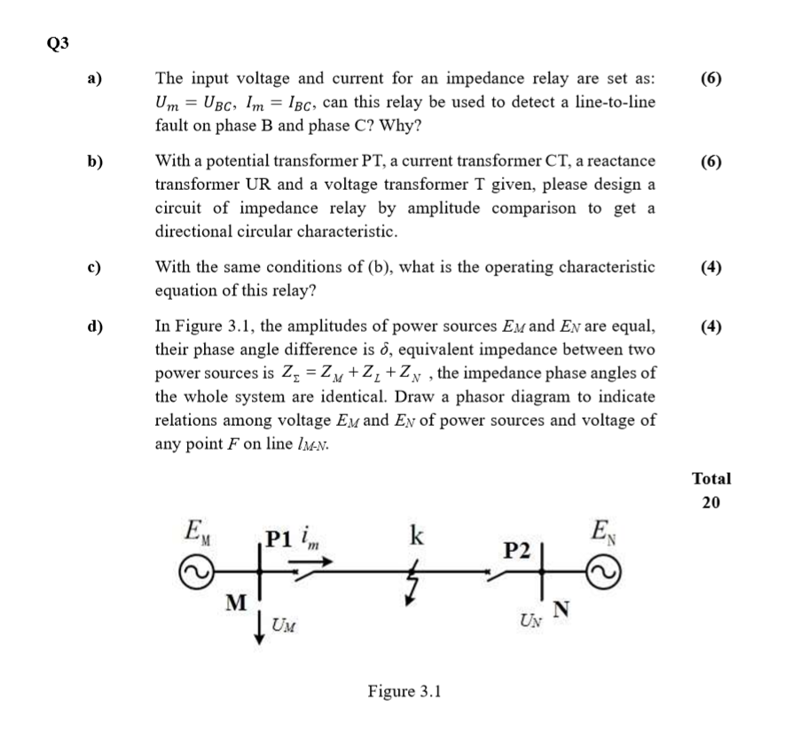
Q3 a) (6) b) (6) c) The input voltage and current for an impedance relay are set as: Um = UBC, Im = lbc, can this relay be used to detect a line-to-line fault on phase B and phase C? Why? With a potential transformer PT, a current transformer CT, a reactance transformer UR and a voltage transformer T given, please design a circuit of impedance relay by amplitude comparison to get a directional circular characteristic. With the same conditions of (b), what is the operating characteristic equation of this relay? In Figure 3.1, the amplitudes of power sources Em and En are equal, their phase angle difference is o, equivalent impedance between two power sources is Zz = Zn +2, +Zy , the impedance phase angles of the whole system are identical. Draw a phasor diagram to indicate relations among voltage Em and Ey of power sources and voltage of any point F on line Im-N. (4) d) (4) Total 20 EX P1 in k EN P2 M N tu UM UN Figure 3.1 Q3 a) (6) b) (6) c) The input voltage and current for an impedance relay are set as: Um = UBC, Im = lbc, can this relay be used to detect a line-to-line fault on phase B and phase C? Why? With a potential transformer PT, a current transformer CT, a reactance transformer UR and a voltage transformer T given, please design a circuit of impedance relay by amplitude comparison to get a directional circular characteristic. With the same conditions of (b), what is the operating characteristic equation of this relay? In Figure 3.1, the amplitudes of power sources Em and En are equal, their phase angle difference is o, equivalent impedance between two power sources is Zz = Zn +2, +Zy , the impedance phase angles of the whole system are identical. Draw a phasor diagram to indicate relations among voltage Em and Ey of power sources and voltage of any point F on line Im-N. (4) d) (4) Total 20 EX P1 in k EN P2 M N tu UM UN Figure 3.1
Step by Step Solution
There are 3 Steps involved in it

Get step-by-step solutions from verified subject matter experts