

Question
This is for computer organization. Any help is much appreciated! Suppose the following instruction is fetched by a processor with a single-cycle datapath such as
This is for computer organization. Any help is much appreciated!
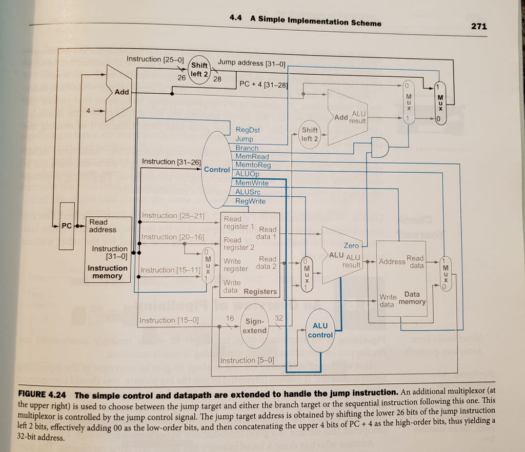
Suppose the following instruction is fetched by a processor with a single-cycle datapath such as the one shown in Figure 4.24
1010 1100 0110 0010 0000 0000 0001 0100
The data memory is all 0s and the registers contain the following values at the beginning of the cycle.

What are the values of the ALUOp and ALUSrc for this instruction?
Thank you for your help!
4.4 A Simple Implementation Scheme 271 Instruction [25-0 Shift left 2 Jump address [31-o] 26 e"728 | PC + 4 [31-28] Add MI 4 Add ALU result RegDst Jump Branch MemRead Shift left 2 Instruction [31-26] Control MemtoReg MemWrite ALUSrc RegWrite Instruction (25-21] Read Read PC address register 1 Read data 1 Instruction [20-16) Read Instruction 1 register 2 M | | Zero 31-0] (ALUA ALUAddress dataM result Read Write Read instruction |||Instruction [15-1111 register data 21 register dataSHt memory Write data Registers Write Data data memory 16 Sign- extend Instruction [15-0] ALU control instruction [5-0] FIGURE 4.24 The simple control and datapath are extended to handle the jump instruction. An additional multiplexor (at the upper right) is used to choose between the jump target and either the branch target or the sequential instruction following th multiplexor is controlled by the jump control signal. The jump target address is obtained by shifting the lower 26 bits of the jump instruction left 2 bits, effectively adding 00 as the low-order bits, and then concatenating the upper 4 bits of PC+ 4 as the high-order bits, thus yielding a 32-bit address. 4.4 A Simple Implementation Scheme 271 Instruction [25-0 Shift left 2 Jump address [31-o] 26 e"728 | PC + 4 [31-28] Add MI 4 Add ALU result RegDst Jump Branch MemRead Shift left 2 Instruction [31-26] Control MemtoReg MemWrite ALUSrc RegWrite Instruction (25-21] Read Read PC address register 1 Read data 1 Instruction [20-16) Read Instruction 1 register 2 M | | Zero 31-0] (ALUA ALUAddress dataM result Read Write Read instruction |||Instruction [15-1111 register data 21 register dataSHt memory Write data Registers Write Data data memory 16 Sign- extend Instruction [15-0] ALU control instruction [5-0] FIGURE 4.24 The simple control and datapath are extended to handle the jump instruction. An additional multiplexor (at the upper right) is used to choose between the jump target and either the branch target or the sequential instruction following th multiplexor is controlled by the jump control signal. The jump target address is obtained by shifting the lower 26 bits of the jump instruction left 2 bits, effectively adding 00 as the low-order bits, and then concatenating the upper 4 bits of PC+ 4 as the high-order bits, thus yielding a 32-bit addressStep by Step Solution
There are 3 Steps involved in it
Step: 1

Get Instant Access to Expert-Tailored Solutions
See step-by-step solutions with expert insights and AI powered tools for academic success
Step: 2

Step: 3
Ace Your Homework with AI
Get the answers you need in no time with our AI-driven, step-by-step assistance
Get Started
Introductory Relational Database Design For Business With Microsoft Access
Authors: Jonathan Eckstein, Bonnie R. Schultz
1st Edition
1119329418, 978-1119329411