Answered step by step
Verified Expert Solution
Question
1 Approved Answer
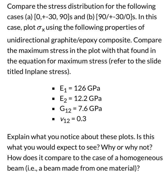
This Matlab script results in a plot of the internal stresses in a %laminated beam under a 3 point bend test close all; clear all;
This Matlab script results in a plot of the internal stresses in a
%laminated beam under a 3 point bend test
close all;
clear all;
%define material properties
% Material Name
% E1 = ;
% E2 = ;
% G12 =;
% v12 =;
%derived
v21 = v12*(E2/E1);
%%%%%%%%%%%%%%%% build required components of the laminate and its layers
% Define laminate dimensions
length = ;
width = ;
laminateThickness = ;
%define load conditions
P = 10;
M = -P*length/2.0; %M = Px/2 - max occurs at L/2
%Set up the laminate layers
numberofLayers =;
% set the ply angle of each layer
% plyAngle(1) = ;
% plyAngle(2) = ;
% and so on for each layer
%set the ply thickness
plyThickness = (laminateThicknessumberofLayers)*ones(numberofLayers);
%define the bottom and top of each layer and store in the vector z
z = .5: -.25: -.5;
% this is an example for a 1 in thick symmetric laminate
% creates a vector (0.5, .25, 0, -.25, -.5). This works fine since the
% laminate is symmetric with respect to the thickness of each ply.
% Otherwise you would have to do it manually
%%%%%%%%%%%%%%%%%% General Calculations %%%%%%%%%%01%%10%%%%%%%%%%%%%%%%%%
%define and zero any required arrays
D = zeros(3,3);
f = zeros(3);
stress = zeros(3);
plyArea = zeros(numberofLayers);
zClPly = zeros(numberofLayers);
I = zeros(numberofLayers);
% calculate Ix for each ply using the parallel axis theorem
% This summation technique is not necessary for this problem set. However,
% you should have it ready to go from last week. If you want you could
% just use
% Ix = base*height^3/12
%
% for i=1:numberofLayers
% plyArea(i) = width*plyThickness(i);
% zClPly(i) = (z(i) + z(i+1))/2; %works for this setup
% I(i) = width*plyThickness(i)^3/12 + plyArea(i)*zClPly(i)^2;
% end
% Ix = sum(I,'all'); %note for a symmetric laminate with all of the plys
% having the same dimensions this should equal base*height^3/12. It is a
% good way to check the results
% compute Qbar and the bending matrix, D using a for-loop
for i=1:numberofLayers
%fill in required function calls here for Qbar and D
end
%%%%% determine stresses
% define and intialize any arrays
sigmax = zeros(2*numberofLayers); % store stresses here
sigmaxy = zeros(2*numberofLayers);
sigmaxyBeamTheory = zeros(2*numberofLayers);
y = zeros(2*numberofLayers); % store z coordinates here
xBeamTheory = zeros(2*numberofLayers);
%% these are to store results for plotting
count = 1;
index = 1;
for i=1:numberofLayers
%find the ply stress functions, f, here.
count = i; %this is a variable that goes from 1 to number of layers + 1 it
% helps to track the top and bottom stress component
%determine the stress at the top and bottom of each layer
% this is done below for the analytical approach explained in the notes
% and also using beam theory (xBeamTheory). The beam theory results
% will line up well for the unidirectional lamainate (i.e., [0]4) but
% not for the others. Having it there will help explain the load
% distribution
for j=1:2
[stress] = LaminaeStress(z(count), f, M, Ix); %3 dimensional stress vector
sigmax(index) = stress(1); %lets just store sigma_x for plotting
y(index) = z(count);
xBeamTheory(index) = M*y(index)/Ix;
count = count + 1;
index = index + 1;
end
end
figure
plot(sigmax(:,1), y(:,1),'-r', xBeamTheory(:,1), y(:,1), '--g')
ax = gca;
ax.YGrid = 'on';
yticks([-.5,-.375, -.25, -.125, 0, .125, .25, .375, .5])
xlabel('\sigma_x (psi)');
ylabel('z(in)');
legend('Composite', 'Beam Theory')
%%%%%%%%%%%%%%%%%%%%%%%%% User Defined Functions 1108011 %%%%%%%%%%%%%%%%%%%%%%%%%%
function [stress] = LaminaeStress(z, f, M, Ixx)
%calculation the stresses here. There is one example. You need to fill in
%the other two
stress(1) = z*f(1)*M/Ixx;
end
function [f] = PlyStressFunction(Q, D, h)
%enter the ply stress functions here.
%details of those equations since the indicies are a bit abnormal
end
function [D] = BendingMatrix(Dprevious, Qbar, ztop, zbottom)
%enter the equation for the bending matrix here
end
function [Qbar] = ReducedStiffnessMatrix(E1, E2, G12, v12, v21, theta)
%enter the equations required to compute the reduced stiffness matrix
%here
end

Step by Step Solution
There are 3 Steps involved in it
Step: 1

Get Instant Access to Expert-Tailored Solutions
See step-by-step solutions with expert insights and AI powered tools for academic success
Step: 2

Step: 3

Ace Your Homework with AI
Get the answers you need in no time with our AI-driven, step-by-step assistance
Get Started


