

Question: This problem is related to RISC V architecture, kindly answer all. Design instructional pipelines with minimal hazards Consider the 6-stage pipelined processor as shown below.
This problem is related to RISC V architecture, kindly answer all.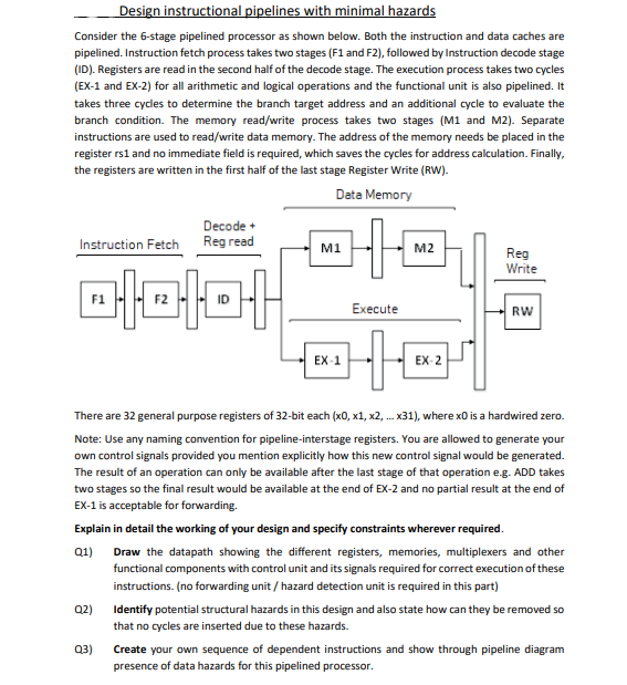
Design instructional pipelines with minimal hazards Consider the 6-stage pipelined processor as shown below. Both the instruction and data caches are pipelined. Instruction fetch process takes two stages (F1 and F2), followed by Instruction decode stage (ID). Registers are read in the second half of the decode stage. The execution process takes two cycles (EX-1 and EX-2) for all arithmetic and logical operations and the functional unit is also pipelined. It takes three cycles to determine the branch target address and an additional cycle to evaluate the branch condition. The memory read/write process takes two stages (M1 and M2). Separate instructions are used to read/write data memory. The address of the memory needs be placed in the register rs1 and no immediate field is required, which saves the cycles for address calculation. Finally, the registers are written in the first half of the last stage Register Write (RW). There are 32 general purpose registers of 32 -bit each (x0,x1,x2,x31), where x0 is a hardwired zero. Note: Use any naming convention for pipeline-interstage registers. You are allowed to generate your own control signals provided you mention explicitly how this new control signal would be generated. The result of an operation can only be available after the last stage of that operation e.g. ADD takes two stages so the final result would be available at the end of EX-2 and no partial result at the end of EX- 1 is acceptable for forwarding. Explain in detail the working of your design and specify constraints wherever required. Q1) Draw the datapath showing the different registers, memories, multiplexers and other functional components with control unit and its signals required for correct execution of these instructions. (no forwarding unit / hazard detection unit is required in this part) Q2) Identify potential structural hazards in this design and also state how can they be removed so that no cycles are inserted due to these hazards. Q3) Create your own sequence of dependent instructions and show through pipeline diagram presence of data hazards for this pipelined processor. Q4) Design a Forwarding Unit for the execution unit (EX-1) that can reduce the stalls introduced due to data hazards for your sequence. Write the necessary conditions for this unit and show the final design including all possible forwarding paths with correct inputs and outputs. Does this unit also solve the dependency between an instruction and 'Load'? Q5) Sequences involving 'Store' are still not solved. Design another Forwarding Unit for the memory stage (M1) that can reduce the stalls introduced due to data hazards involving 'Store' instructions. Again, write the necessary conditions for this forwarding unit and show the paths along with all inputs and outputs. Q6) Since all the stalls are not completely eliminated we would need another circuit to detect the data hazards. Design the Hazard Detection Unit (HDU) for detecting the above hazards. An HDU can only insert a single stall each cycle. Moreover, also specify which registers are required to remain unchanged with the insertion of stall. Draw the final design of the ID stage showing HDU's input and outputs. Q7) With this pipeline the branch target address is computed in the third cycle and the branch condition in EX-1. Determine how many stall cycles are inserted for a taken branch. Q8) If the comparator for the branch condition evaluation is moved to the ID stage it will reduce the stalls for control hazards. However, this may result in additional data hazard stall cycles if the branch is dependent on the previous instruction. Write the conditions for detecting this hazard thereby updating the previous HDU
Step by Step Solution
There are 3 Steps involved in it

Get step-by-step solutions from verified subject matter experts