this question is for computer science, so the reposted answer to this question that uses electrical engineering terms makes no sense.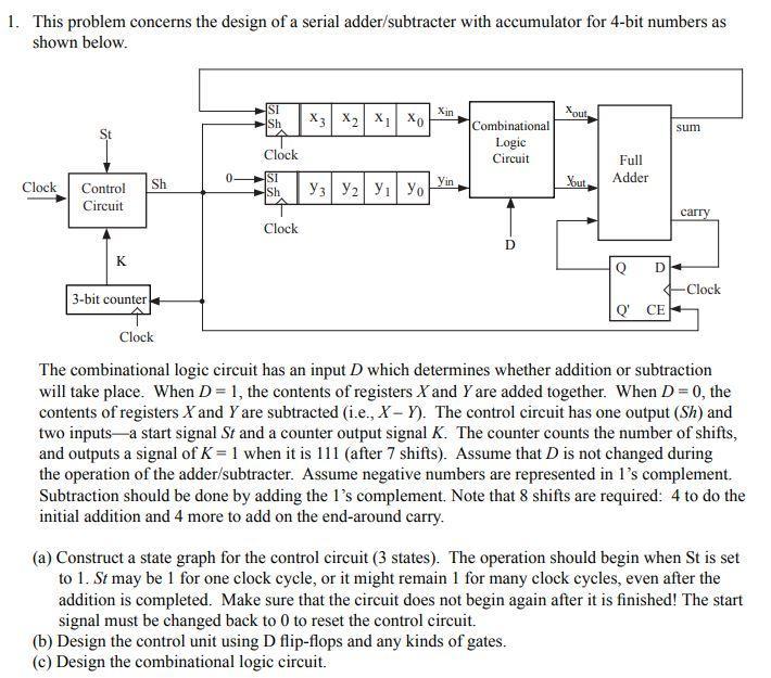
1. This problem concerns the design of a serial adder/subtracter with accumulator for 4-bit numbers as shown below. SI Sh Xin Xout X3 X2 XI XD sum Combinational Logic Circuit Clock Full Adder SI Sh Yin Clock Yout sh Control Circuit | | | carry Clock D D K Q Clock 3-bit counter QCE Clock The combinational logic circuit has an input D which determines whether addition or subtraction will take place. When D = 1, the contents of registers X and Y are added together. When D = 0, the contents of registers X and Y are subtracted (i.e., X - Y). The control circuit has one output (Sh) and two inputsa start signal St and a counter output signal K. The counter counts the number of shifts, and outputs a signal of K = 1 when it is 111 (after 7 shifts). Assume that D is not changed during the operation of the adder/subtracter. Assume negative numbers are represented in l's complement. Subtraction should be done by adding the l's complement. Note that 8 shifts are required: 4 to do the initial addition and 4 more to add on the end-around carry. (a) Construct a state graph for the control circuit (3 states). The operation should begin when St is set to 1. St may be 1 for one clock cycle, or it might remain 1 for many clock cycles, even after the addition is completed. Make sure that the circuit does not begin again after it is finished! The start signal must be changed back to 0 to reset the control circuit. (b) Design the control unit using D flip-flops and any kinds of gates. (c) Design the combinational logic circuit. 1. This problem concerns the design of a serial adder/subtracter with accumulator for 4-bit numbers as shown below. SI Sh Xin Xout X3 X2 XI XD sum Combinational Logic Circuit Clock Full Adder SI Sh Yin Clock Yout sh Control Circuit | | | carry Clock D D K Q Clock 3-bit counter QCE Clock The combinational logic circuit has an input D which determines whether addition or subtraction will take place. When D = 1, the contents of registers X and Y are added together. When D = 0, the contents of registers X and Y are subtracted (i.e., X - Y). The control circuit has one output (Sh) and two inputsa start signal St and a counter output signal K. The counter counts the number of shifts, and outputs a signal of K = 1 when it is 111 (after 7 shifts). Assume that D is not changed during the operation of the adder/subtracter. Assume negative numbers are represented in l's complement. Subtraction should be done by adding the l's complement. Note that 8 shifts are required: 4 to do the initial addition and 4 more to add on the end-around carry. (a) Construct a state graph for the control circuit (3 states). The operation should begin when St is set to 1. St may be 1 for one clock cycle, or it might remain 1 for many clock cycles, even after the addition is completed. Make sure that the circuit does not begin again after it is finished! The start signal must be changed back to 0 to reset the control circuit. (b) Design the control unit using D flip-flops and any kinds of gates. (c) Design the combinational logic circuit