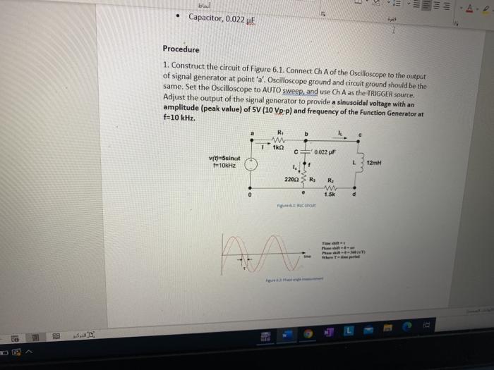
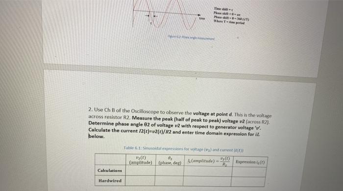
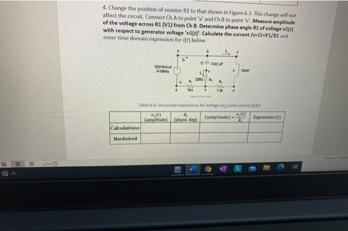
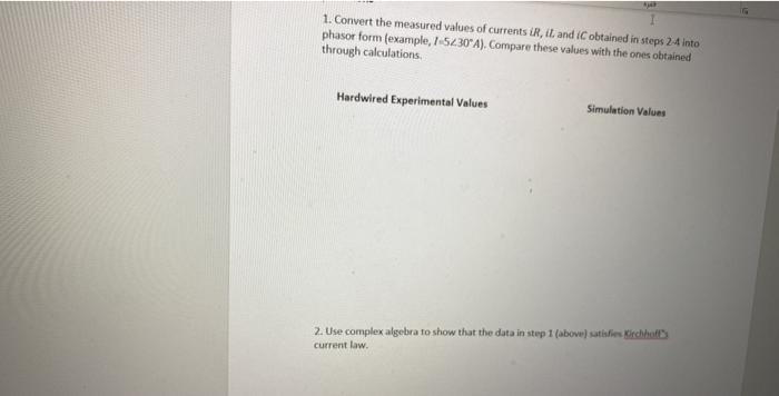
!!! tili A Capacitor, 0.022 st Procedure 1. Construct the circuit of Figure 6.1. Connect Ch A of the Oscilloscope to the output of signal generator at point 'a'. Oscilloscope ground and circuit ground should be the same. Set the Oscilloscope to AUTO sweep, and use Ch A as the TRIGGER source. Adjust the output of the signal generator to provide a sinusoidal voltage with an amplitude (peak value) of SV (10 VP-P) and frequency of the Function Generator at f=10 kHz. b w 122 1 0.022 pF (t)=sinot f10kHz L 12mH 2200 R R. WW 1.5K Cut Thes w Phase WT My 2. Use Ch B of the Oscilloscope to observe the voltage at point d. This is the voltage across resistor R2. Measure the peak (half of peak to peak) voltage v2 (across R2). Determine phase angle 82 of voltage v2 with respect to generator voltage'v. Calculate the current 12(t)=v2(c)/R2 and enter time domain expression for it below. Table 1: Sinusoidal expressions for voltage and current (t) 82 (0) (amplitude) (phase, deg) le (amplitude) - Expression) Calculations Hardwired 3. Move Ch B of the Oscilloscope to observe the voltage at point. This is the voltage across R3. Measure the amplitude 3 and phase 83 with respect to ty. Calculate the current iC (13(t)/R3) and enter time domain expression for it) below Table Sesdal expressions for its and current (+) (amplitude) (phase, del cumplitude) - Expressione R Calculation Hardwired 4. Change the position of resistor R1 to that shown in Figure 6.3. This change will not affect the circuit. Connect Ch A to point and Ch B to point 'e'. Measure amplitude of the voltage across R1 (v1) from Ch B. Determine phase angle 81 of voltage v1(1) with respect to generator voltage 'vllt). Calculate the current/s/1=V1/R1 and enter time domain expression for it) below. c0003 VO 10 120 220) RA N. M w 1.56 th Table 6: sinusoidal expressions for voltage and current (amplitude) (phase, der) (amplitude) RA Expression (0) Calculations Hardwired 1. Convert the measured values of currents ir, it, and obtained in steps 2.4 into phasor form (example, I-5230 A). Compare these values with the ones obtained through calculations Hardwired Experimental Values Simulation Values 2. Use complex algebra to show that the data in step 1 (above) satisfies Kirchhof current law. !!! tili A Capacitor, 0.022 st Procedure 1. Construct the circuit of Figure 6.1. Connect Ch A of the Oscilloscope to the output of signal generator at point 'a'. Oscilloscope ground and circuit ground should be the same. Set the Oscilloscope to AUTO sweep, and use Ch A as the TRIGGER source. Adjust the output of the signal generator to provide a sinusoidal voltage with an amplitude (peak value) of SV (10 VP-P) and frequency of the Function Generator at f=10 kHz. b w 122 1 0.022 pF (t)=sinot f10kHz L 12mH 2200 R R. WW 1.5K Cut Thes w Phase WT My 2. Use Ch B of the Oscilloscope to observe the voltage at point d. This is the voltage across resistor R2. Measure the peak (half of peak to peak) voltage v2 (across R2). Determine phase angle 82 of voltage v2 with respect to generator voltage'v. Calculate the current 12(t)=v2(c)/R2 and enter time domain expression for it below. Table 1: Sinusoidal expressions for voltage and current (t) 82 (0) (amplitude) (phase, deg) le (amplitude) - Expression) Calculations Hardwired 3. Move Ch B of the Oscilloscope to observe the voltage at point. This is the voltage across R3. Measure the amplitude 3 and phase 83 with respect to ty. Calculate the current iC (13(t)/R3) and enter time domain expression for it) below Table Sesdal expressions for its and current (+) (amplitude) (phase, del cumplitude) - Expressione R Calculation Hardwired 4. Change the position of resistor R1 to that shown in Figure 6.3. This change will not affect the circuit. Connect Ch A to point and Ch B to point 'e'. Measure amplitude of the voltage across R1 (v1) from Ch B. Determine phase angle 81 of voltage v1(1) with respect to generator voltage 'vllt). Calculate the current/s/1=V1/R1 and enter time domain expression for it) below. c0003 VO 10 120 220) RA N. M w 1.56 th Table 6: sinusoidal expressions for voltage and current (amplitude) (phase, der) (amplitude) RA Expression (0) Calculations Hardwired 1. Convert the measured values of currents ir, it, and obtained in steps 2.4 into phasor form (example, I-5230 A). Compare these values with the ones obtained through calculations Hardwired Experimental Values Simulation Values 2. Use complex algebra to show that the data in step 1 (above) satisfies Kirchhof current law


