Answered step by step
Verified Expert Solution
Question
1 Approved Answer
To create an improved network diagram using draw.io , I'll provide a detailed description of how to structure it based on the given requirements. The
To create an improved network diagram using draw.io I'll provide a detailed description of how to structure it based on the given requirements. The key components you need to include are:
Explanation:
VPC
Public and Private Subnets
Internet Gateway
NAT Gateway or NAT Instance
Elastic Load Balancer
Auto Scaling Group
Application Servers
RDS Databases
Security Groups
Network ACLs
Step
Heres how to design the architecture:
Explanation:
VPC:
Create a VPC to enclose all resources.
Subnets:
Public Subnet Contains the Load Balancer, NAT GatewayInstance
Private Subnet Contains the Application Servers and RDS Databases
Internet Gateway:
Attach an Internet Gateway to the VPC
NAT GatewayInstance:
Place the NAT GatewayInstance in the Public Subnet.
Elastic Load Balancer ELB:
Place the ELB in the Public Subnet.
Auto Scaling Group:
Configure an Auto Scaling Group behind the ELB to manage Application Server instances in the Private Subnet.
Application Servers:
Deploy Application Servers in the Private Subnet, managed by the Auto Scaling Group.
RDS Databases:
Deploy a master RDS instance in one Availability Zones Private Subnet.
Deploy a standby RDS instance in another Availability Zones Private Subnet.
Security Groups:
Create Security Groups to control access to the ELB, Application Servers, and RDS instances.
Network ACLs:
Apply Network ACLs to the subnets for additional security.
StepbyStep Drawing on draw.io
Create the Main VPC Container:
Use a rectangle to represent the VPC Label it VPC
Add Subnets:
Draw two rectangles inside the VPC for the Public Subnet and Private Subnet. Label them accordingly.
Internet Gateway:
Place an icon or shape for the Internet Gateway on the edge of the VPC
NAT GatewayInstance:
Place an icon for the NAT GatewayInstance inside the Public Subnet.
Elastic Load Balancer:
Place an ELB icon inside the Public Subnet.
Auto Scaling Group:
Inside the Private Subnet, indicate the Auto Scaling Group with multiple server icons or a scalable group icon.
Application Servers:
Within the Auto Scaling Group, add icons for Application Servers.
RDS Databases:
Add RDS icons in the Private Subnet, with one master instance in one AZ and a standby instance in another AZ
Security Groups:
Draw circles or use icons to represent Security Groups around the ELB, Application Servers, and RDS instances.
Network ACLs:
Indicate Network ACLs at the subnet boundaries.
Connections and Arrows:
Draw arrows to represent the flow of traffic:
From the Internet to the Internet Gateway.
From the Internet Gateway to the ELB.
From the ELB to the Application Servers.
From the Application Servers to the RDS instances.
From the NAT GatewayInstance to the Application Servers for outbound internet access.
You can use the provided bootstrap script to configure your servers:
#binbash
yum update y
yum install httpd y
service httpd start
chkconfig httpd on
cd varwwwhtml
echo "Hello World from Server index.html
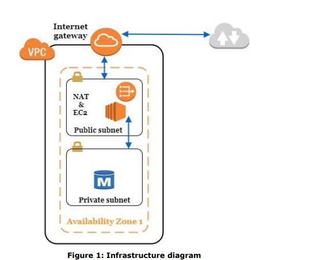
Use the description and the step by step procedure above and the picture i uploaded to draw a diagram of an illustrated improved architecturenetwork diagram. DRAW the diagram on draw.io FOR ME PLEASE

Step by Step Solution
There are 3 Steps involved in it
Step: 1

Get Instant Access to Expert-Tailored Solutions
See step-by-step solutions with expert insights and AI powered tools for academic success
Step: 2

Step: 3

Ace Your Homework with AI
Get the answers you need in no time with our AI-driven, step-by-step assistance
Get Started


