Answered step by step
Verified Expert Solution
Link Copied!

Question

1 Approved Answer

Two switches SWI and SW2 are connected to port E pins PE1 and PE2, respectively as shown in Figure 8.22. Pressing switch SW1 each time

Two switches SWI and SW2 are connected to port E pins PE1 and PE2, respectively as shown in Figure 8.22. Pressing switch SW1 each time toggles red LED connected to PF1, while pressing SW2 toggles blue LED connected to PF2. witea Biogram that performs the desired operation. Configure all the necessary GPIO registers.

Nov are free to write your program using either poling or interrupt based approach.
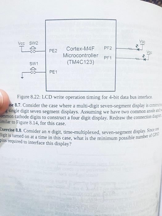
image text in transcribed
Figure 8.22: LCD write operation timing for 4-bit data bus interface. ise 8.7. Consider the case where a multi-digit seven-segment display is construtt 6 single digit seven segment displays. Assuming we have two common anode ant ommon cathode digits to construct a four digit display. Redraw the connection diagen imilar to Figure 8.14, for this case. Exercise 8.8. Consider an n digit, time-multiplexed, seven-segment display. Since one: digit is turned on at a time in this case, what is the minimum possible number of GP10 pins required to interface this display

Step by Step Solution

There are 3 Steps involved in it

Step: 1

blur-text-image

Get Instant Access to Expert-Tailored Solutions

See step-by-step solutions with expert insights and AI powered tools for academic success

Step: 2

blur-text-image

Step: 3

blur-text-image

Ace Your Homework with AI

Get the answers you need in no time with our AI-driven, step-by-step assistance

Get Started

Recommended Textbook for

Spatio Temporal Database Management International Workshop Stdbm 99 Edinburgh Scotland September 10 11 1999 Proceedings Lncs 1678

Authors: Michael H. Bohlen ,Christian S. Jensen ,Michel O. Scholl

1999th Edition

3540664017, 978-3540664017

More Books

Students also viewed these Databases questions