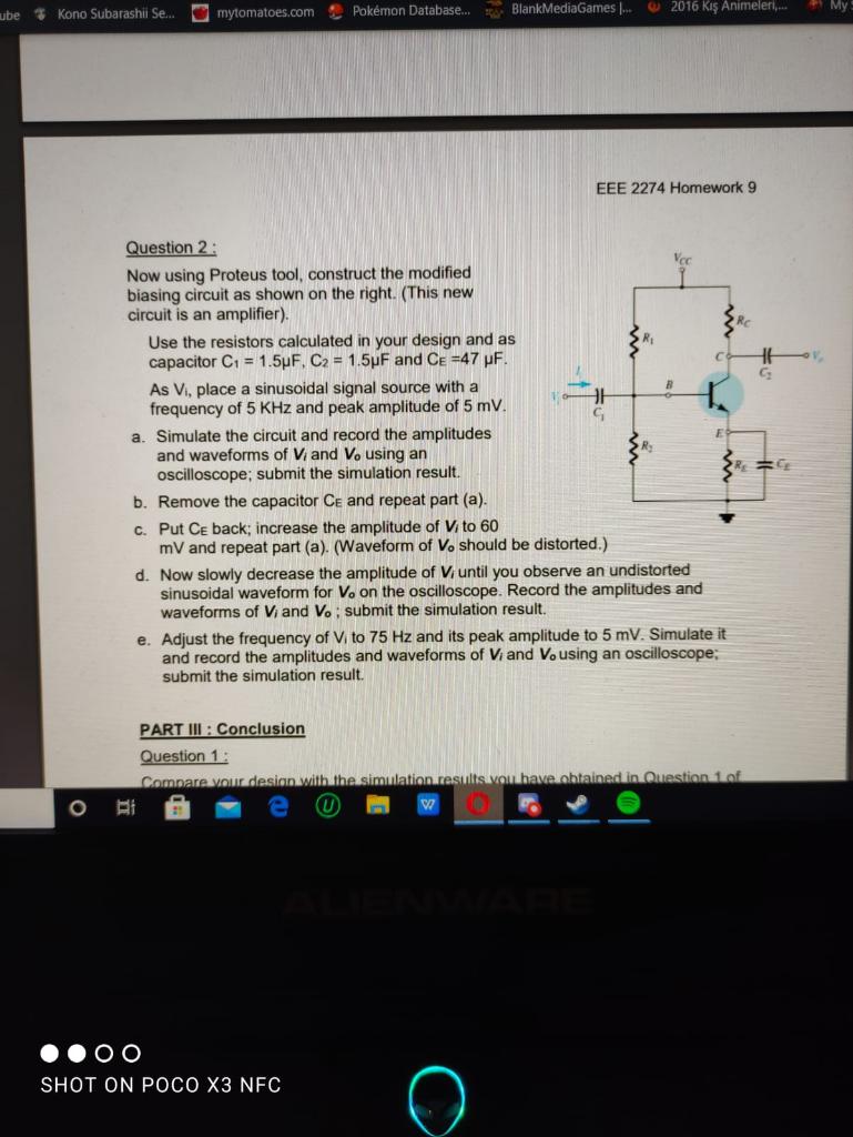
ube Kono Subarashii Se... mytomatoes.com Pokmon Database... BlankMediaGames 2016 K Animeleri... My EEE 2274 Homework 9 G G Question 2 : Veo Now using Proteus tool, construct the modified biasing circuit as shown on the right. (This new circuit is an amplifier). Use the resistors calculated in your design and as capacitor C1 = 1.5uF. C2 = 1.5 F and CE =47 uF. As Vi, place a sinusoidal signal source with a 8 frequency of 5 KHz and peak amplitude of 5 mV. a. Simulate the circuit and record the amplitudes and waveforms of Vand Vo using an oscilloscope; submit the simulation result. b. Remove the capacitor Ce and repeat part (a). c. Put Ce back; increase the amplitude of Vito 60 mV and repeat part (a). (Waveform of V, should be distorted.) d. Now slowly decrease the amplitude of Viuntil you observe an undistorted sinusoidal waveform for Ve on the oscilloscope. Record the amplitudes and waveforms of Vi and Vo: submit the simulation result. e. Adjust the frequency of V to 75 Hz and its peak amplitude to 5 mV. Simulate it and record the amplitudes and waveforms of Vi and Vousing an oscilloscope; submit the simulation result. PART III : Conclusion Question 1: Compare your desian with the simulation results you have obtained in Question of W SHOT ON POCO X3 NFC o submit the simulation result. PART III : Conclusion Question 1: Compare your design with the simulation results you have obtained in Question 1 of Part II and explain the reasons for the differences that you may have observed. Question 2 : a. Recall that voltage gain of an amplifier is defined as the ratio of output voltage amplitude to input voltage amplitude. Calculate the voltage gain of the amplifier in Question 2 of Part II, for the two cases: i) with CE: ii) without CE. Comment on how the existence of Ce affects the voltage gain b. Considering the results of part (c) and (d) of Question 2 of Part II, comment on why the amplitude of input voltage affects the output waveform. c. Calculate the voltage gain for the case part (e) of Question 2 of Part II, and comment on why the frequency of input voltage affects the voltage gain. o - OO SHOT ON POCO X3 NFC FE F9 FO F7 ES FL F6 ube Kono Subarashii Se... mytomatoes.com Pokmon Database... BlankMediaGames 2016 K Animeleri... My EEE 2274 Homework 9 G G Question 2 : Veo Now using Proteus tool, construct the modified biasing circuit as shown on the right. (This new circuit is an amplifier). Use the resistors calculated in your design and as capacitor C1 = 1.5uF. C2 = 1.5 F and CE =47 uF. As Vi, place a sinusoidal signal source with a 8 frequency of 5 KHz and peak amplitude of 5 mV. a. Simulate the circuit and record the amplitudes and waveforms of Vand Vo using an oscilloscope; submit the simulation result. b. Remove the capacitor Ce and repeat part (a). c. Put Ce back; increase the amplitude of Vito 60 mV and repeat part (a). (Waveform of V, should be distorted.) d. Now slowly decrease the amplitude of Viuntil you observe an undistorted sinusoidal waveform for Ve on the oscilloscope. Record the amplitudes and waveforms of Vi and Vo: submit the simulation result. e. Adjust the frequency of V to 75 Hz and its peak amplitude to 5 mV. Simulate it and record the amplitudes and waveforms of Vi and Vousing an oscilloscope; submit the simulation result. PART III : Conclusion Question 1: Compare your desian with the simulation results you have obtained in Question of W SHOT ON POCO X3 NFC o submit the simulation result. PART III : Conclusion Question 1: Compare your design with the simulation results you have obtained in Question 1 of Part II and explain the reasons for the differences that you may have observed. Question 2 : a. Recall that voltage gain of an amplifier is defined as the ratio of output voltage amplitude to input voltage amplitude. Calculate the voltage gain of the amplifier in Question 2 of Part II, for the two cases: i) with CE: ii) without CE. Comment on how the existence of Ce affects the voltage gain b. Considering the results of part (c) and (d) of Question 2 of Part II, comment on why the amplitude of input voltage affects the output waveform. c. Calculate the voltage gain for the case part (e) of Question 2 of Part II, and comment on why the frequency of input voltage affects the voltage gain. o - OO SHOT ON POCO X3 NFC FE F9 FO F7 ES FL F6