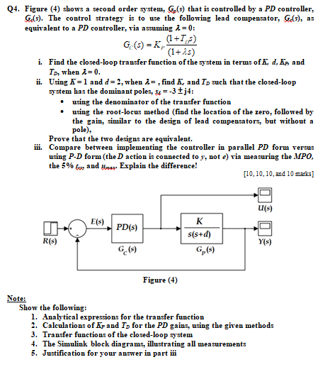
Question: undefined Q4. Figure (4) shows a second order system, G () that is controlled by a PD controller, G.(s). The control strategy is to use
 undefined
Q4. Figure (4) shows a second order system, G () that is controlled by a PD controller, G.(s). The control strategy is to use the following lead compensator, G.s), as equivalent to a PD controller, via assuming i = 0; (1+T ) G (5) =ke (1+25) i. Find the closed-loop transfer function of the system in terms of K, d. As and TD, when i=0. ii. Using K = 1 and d=2, when i= , find K, and Tp such that the closed-loop system has the dominant poles, sa = -3 j4: using the denominator of the transfer function using the root-locus method (find the location of the zero, followed by the gain, similar to the design of lead compensators, but without a pole), Prove that the two designs are equivalent. i. Compare between implementing the controller in parallel PD form versus using P-D form (the action is connected to y, not e) via measuring the MPO, the 5% to and Explain the difference! [10.10.10 and 10 marks] U(s) E(s) PD(S) K s(s+d) R(s) Y(s) Ge(s) Figure (4) Note: Show the following: 1. Analytical expressions for the transfer function 2. Calculations of Epand To for the PD gains, using the given methods 3. Transfer functions of the closed-loop system 4. The Simulink block diagrams, illustrating all measurements 5. Justification for your answer in partii Q4. Figure (4) shows a second order system, G () that is controlled by a PD controller, G.(s). The control strategy is to use the following lead compensator, G.s), as equivalent to a PD controller, via assuming i = 0; (1+T ) G (5) =ke (1+25) i. Find the closed-loop transfer function of the system in terms of K, d. As and TD, when i=0. ii. Using K = 1 and d=2, when i= , find K, and Tp such that the closed-loop system has the dominant poles, sa = -3 j4: using the denominator of the transfer function using the root-locus method (find the location of the zero, followed by the gain, similar to the design of lead compensators, but without a pole), Prove that the two designs are equivalent. i. Compare between implementing the controller in parallel PD form versus using P-D form (the action is connected to y, not e) via measuring the MPO, the 5% to and Explain the difference! [10.10.10 and 10 marks] U(s) E(s) PD(S) K s(s+d) R(s) Y(s) Ge(s) Figure (4) Note: Show the following: 1. Analytical expressions for the transfer function 2. Calculations of Epand To for the PD gains, using the given methods 3. Transfer functions of the closed-loop system 4. The Simulink block diagrams, illustrating all measurements 5. Justification for your answer in partii
Step by Step Solution
There are 3 Steps involved in it

Get step-by-step solutions from verified subject matter experts


