
 USE 8085 simulator to simulate.
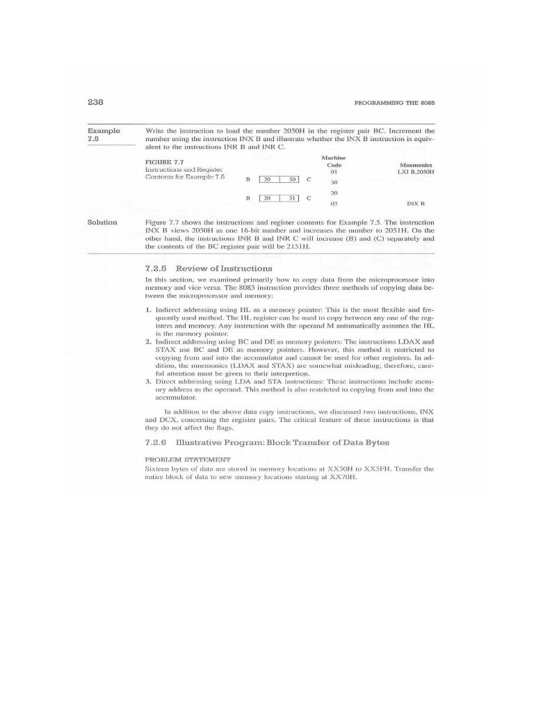
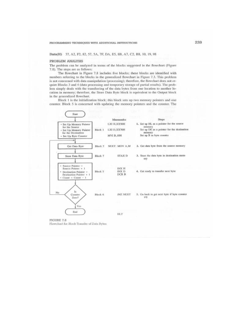
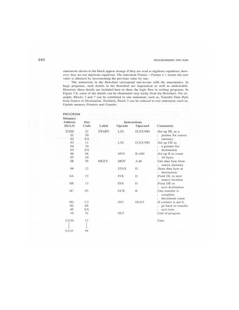
238 PROGRAMMING THE B085 Example 7.5 Write the instruction to loud the number 2050H in the register pair BC. Increment the number using the instruction INX B and illustrate whether the INX B instruction is equiv- alent to the instructions INR Band INRC FIGURE 7.7 Machine Code Instructions and Register Mnemonies 01 Contents for Example 7.5 LXI B.20SOH 30 SO C 50 20 SI 03 INXR Solution Figure 7.7 shows the instructions and register contents for Example 7.5. The instruction INX B views 2050H as one 16-bit number and increases the number to 2051H. On the other hand, the instructions INR B and INR C will increase (B) and (C) neparately and the contents of the BC register pair will be 21511. 7.2.5 Review of Instructions In this section, we examined primarily how to copy data from the microprocessor into memory and vice versa. The 8085 instruction provides three methods of copying data be- tween the microprocessor and memory: 1. Indirect addressing using HL as a memory pointer: This is the most flexible and fre- quently used method. The HL register can be used to copy between any one of the reg isters and memory. Any instruction with the operand M automatically assumes the HL is the memory pointer. 2. Indirect addressing using BC and Deus memory pointers: The instructions LDAX and STAX use BC and DE as memory pointers. However, this method is restricted to copying from and into the accumulator and cannot be used for other registers. In ad- dition, the memonics (LDAX and STAX) are somewhat misleading, cherefore, care ful attention must be given to their interpretion. Direct addressing using LDA and STA Instructions: These instructions include mem- ory address as the operand. This method is also restricted to copying from and into the accumulator In addition to the above data copy instructions, we discussed two instructions, INX and DCX, concerning the register pairs. The critical feature of these instructions is that they do not affect the flags 7.2.6 Illustrative Program: Block Transfer of Data Bytes PROBLEM STATEMENT Sixteen bytes of data me stored in memory locations at XX50H 10 XXSFH. Transfer the entue block of data to new memory locations starting at XX70H, PROGRAMMING TECHNIQUES WITH ADDITIONAL INSTRUCTIONS 239 Data(H) 37. A2, F2, 82, 57, 5A, 7E, DA, E5, 8B, A7, C2, B8, 10, 19.98 , , PROBLEM ANALYSIS The problem can be analyzed in terms of the blocks suggested in the flowchart (Figure 7.8). The steps are as follows: The flowchart in Figure 7.8 includes five blocks; these blocks are identified with numbers referring to the blocks in the generalized flowchart in Figure 7.3. This problem is not concerned with data manipulation (processing); therefore, the flowchart does not re- quire Blocks 3 and 4 (data processing and temporary storage of partial results). The prob- lem simply deals with the transferring of the data bytes from one location to another lo- cation in memory: therefore, the Store Data Byte block is equivalent to the Output block in the generalized flowchart, Block 1 is the initialization block; this block sets up two memory pointers and one counter. Block 5 is concerned with updating the memory pointers and the counter. The Start Mnemoules LXI H.XXSOH Set Up Memory Pointer for the source Set Up Memory Pointer for the Destination Set Up Byle Counter Steps 1. Set up HL a pointer for the source memory Setup DE pointer for the destination memory Set up a byte counter Block 1 LXID XX2011 MVI B, 10H Get Data Byte Block 2 NEXT MOV A.M 2. Get data byte from the source memory Store Data Byte Block 7 STAX D 3. Store the data byte in destination mem ory Source Pointer Source Pointer + 1 Destination Pointer Destination Pointer + 1 Chunt - Count - Blocks INXH INX D DCR 4. Get ready to transfer next byte No Is Counter Zero! Block 6 Block INZ NEXT 5. Go back to get next byte if byte counter 70 Yes FILT FIGURE 7.8 Flowchart for Block Transfer of Data Bytes 240 PROGRAMMING THE 8085 statements shown in the block appear strange if they are read as algebraic equations, how ever, they are not algebraic equations. The statement Pointer Pointer + I means the new value is obtained by incrementing the previous value by one. The statements in the flowchart correspond one-to-one with the mnemonics. In large programs, such details in the flowchart are impractical as well as undesirable. However, these details are included here to show the logic flow in writing programs. In Figure 7.8, some of the details can be eliminated very easily from the flowchart. For ex- ample, Blocks 2 and 7 can be combined in one statement: such as, Transfer Data Byte from Source to Destination. Similarly, Block 5 can be reduced to one statement, such as, Update memory Pointers and Counter Hex Code Instructions Opcode Operand LXI H.XXSOH Label START Comments PROGRAM Memory Address HI-LO XX00 01 02 03 04 os 06 07 08 LXI D.XX70H 21 SO XX 11 20 XX 06 10 7E MVI B.10H NEXT: MOV A.M 09 12 STAX D Set up HL as a pointer for source memory Set up DE ia pointer for destination Set up B to count ; 16 bytes Get data byte from source memory Store data byte al destination Point HL to next : source location Point DE to next destination One transfer is complete, decrement count If counter is not 0, go back to transfer next byte End of program OA 23 INX H OB 13 INX D oc 05 DCR B B JNZ NEXT NEXT OD OE OF 10 08 XX 76 HLT 37 Data XX50 1 XXSF 98 238 PROGRAMMING THE B085 Example 7.5 Write the instruction to loud the number 2050H in the register pair BC. Increment the number using the instruction INX B and illustrate whether the INX B instruction is equiv- alent to the instructions INR Band INRC FIGURE 7.7 Machine Code Instructions and Register Mnemonies 01 Contents for Example 7.5 LXI B.20SOH 30 SO C 50 20 SI 03 INXR Solution Figure 7.7 shows the instructions and register contents for Example 7.5. The instruction INX B views 2050H as one 16-bit number and increases the number to 2051H. On the other hand, the instructions INR B and INR C will increase (B) and (C) neparately and the contents of the BC register pair will be 21511. 7.2.5 Review of Instructions In this section, we examined primarily how to copy data from the microprocessor into memory and vice versa. The 8085 instruction provides three methods of copying data be- tween the microprocessor and memory: 1. Indirect addressing using HL as a memory pointer: This is the most flexible and fre- quently used method. The HL register can be used to copy between any one of the reg isters and memory. Any instruction with the operand M automatically assumes the HL is the memory pointer. 2. Indirect addressing using BC and Deus memory pointers: The instructions LDAX and STAX use BC and DE as memory pointers. However, this method is restricted to copying from and into the accumulator and cannot be used for other registers. In ad- dition, the memonics (LDAX and STAX) are somewhat misleading, cherefore, care ful attention must be given to their interpretion. Direct addressing using LDA and STA Instructions: These instructions include mem- ory address as the operand. This method is also restricted to copying from and into the accumulator In addition to the above data copy instructions, we discussed two instructions, INX and DCX, concerning the register pairs. The critical feature of these instructions is that they do not affect the flags 7.2.6 Illustrative Program: Block Transfer of Data Bytes PROBLEM STATEMENT Sixteen bytes of data me stored in memory locations at XX50H 10 XXSFH. Transfer the entue block of data to new memory locations starting at XX70H, PROGRAMMING TECHNIQUES WITH ADDITIONAL INSTRUCTIONS 239 Data(H) 37. A2, F2, 82, 57, 5A, 7E, DA, E5, 8B, A7, C2, B8, 10, 19.98 , , PROBLEM ANALYSIS The problem can be analyzed in terms of the blocks suggested in the flowchart (Figure 7.8). The steps are as follows: The flowchart in Figure 7.8 includes five blocks; these blocks are identified with numbers referring to the blocks in the generalized flowchart in Figure 7.3. This problem is not concerned with data manipulation (processing); therefore, the flowchart does not re- quire Blocks 3 and 4 (data processing and temporary storage of partial results). The prob- lem simply deals with the transferring of the data bytes from one location to another lo- cation in memory: therefore, the Store Data Byte block is equivalent to the Output block in the generalized flowchart, Block 1 is the initialization block; this block sets up two memory pointers and one counter. Block 5 is concerned with updating the memory pointers and the counter. The Start Mnemoules LXI H.XXSOH Set Up Memory Pointer for the source Set Up Memory Pointer for the Destination Set Up Byle Counter Steps 1. Set up HL a pointer for the source memory Setup DE pointer for the destination memory Set up a byte counter Block 1 LXID XX2011 MVI B, 10H Get Data Byte Block 2 NEXT MOV A.M 2. Get data byte from the source memory Store Data Byte Block 7 STAX D 3. Store the data byte in destination mem ory Source Pointer Source Pointer + 1 Destination Pointer Destination Pointer + 1 Chunt - Count - Blocks INXH INX D DCR 4. Get ready to transfer next byte No Is Counter Zero! Block 6 Block INZ NEXT 5. Go back to get next byte if byte counter 70 Yes FILT FIGURE 7.8 Flowchart for Block Transfer of Data Bytes 240 PROGRAMMING THE 8085 statements shown in the block appear strange if they are read as algebraic equations, how ever, they are not algebraic equations. The statement Pointer Pointer + I means the new value is obtained by incrementing the previous value by one. The statements in the flowchart correspond one-to-one with the mnemonics. In large programs, such details in the flowchart are impractical as well as undesirable. However, these details are included here to show the logic flow in writing programs. In Figure 7.8, some of the details can be eliminated very easily from the flowchart. For ex- ample, Blocks 2 and 7 can be combined in one statement: such as, Transfer Data Byte from Source to Destination. Similarly, Block 5 can be reduced to one statement, such as, Update memory Pointers and Counter Hex Code Instructions Opcode Operand LXI H.XXSOH Label START Comments PROGRAM Memory Address HI-LO XX00 01 02 03 04 os 06 07 08 LXI D.XX70H 21 SO XX 11 20 XX 06 10 7E MVI B.10H NEXT: MOV A.M 09 12 STAX D Set up HL as a pointer for source memory Set up DE ia pointer for destination Set up B to count ; 16 bytes Get data byte from source memory Store data byte al destination Point HL to next : source location Point DE to next destination One transfer is complete, decrement count If counter is not 0, go back to transfer next byte End of program OA 23 INX H OB 13 INX D oc 05 DCR B B JNZ NEXT NEXT OD OE OF 10 08 XX 76 HLT 37 Data XX50 1 XXSF 98


 USE 8085 simulator to simulate.


