

Question: Use any ARM assembly simulator you'd like but we use keil uvision5 ;;; Directives PRESERVE8 THUMB ; Vector Table Mapped to Address 0 at Reset
Use any ARM assembly simulator you'd like but we use keil uvision5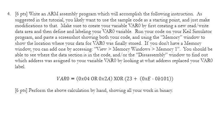
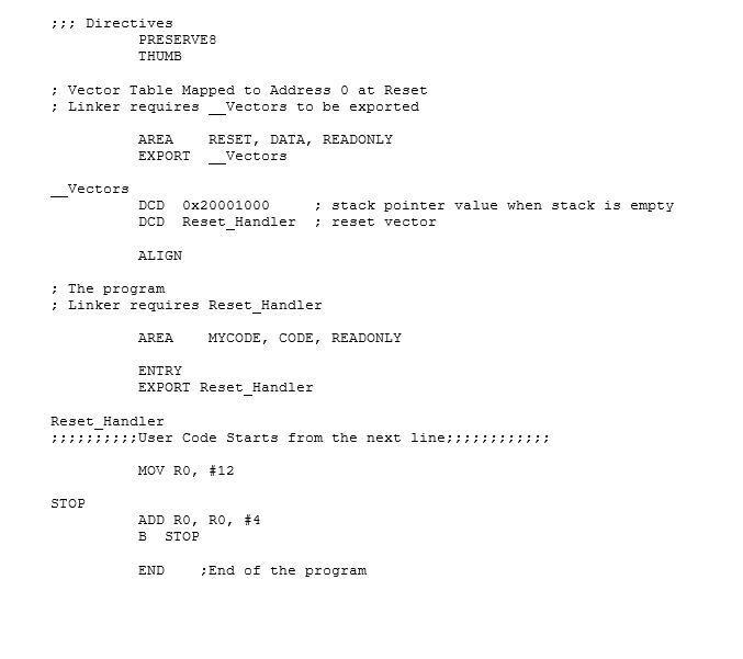
;;; Directives
PRESERVE8
THUMB
; Vector Table Mapped to Address 0 at Reset
; Linker requires __Vectors to be exported
AREA RESET, DATA, READONLY
EXPORT __Vectors
__Vectors
DCD 0x20001000 ; stack pointer value when stack is empty
DCD Reset_Handler ; reset vector
ALIGN
; The program
; Linker requires Reset_Handler
AREA MYCODE, CODE, READONLY
ENTRY
EXPORT Reset_Handler
Reset_Handler
;;;;;;;;;;User Code Starts from the next line;;;;;;;;;;;;
MOV R0, #12
STOP
ADD R0, R0, #4
B STOP
END ;End of the program
4. [6 pts] Write an ARM assembly program which will accomplish the following instruction. As suggested in the tutorial, you likely want to use the sample code as a starting point, and just make modifications to that. Make sure to create your variable VARO by first creating a new read/write data area and then define and labeling your VARO variable. Run your code on your Keil Simulator program, and paste a screenshot showing both your code, and using the "Memory" window to show the location where your data for VARO was finally stored. If you don't have a Memory window, you can add one by accessing: View > Memory Windows > Memory 1. You should be able to see where the data section is in the code, and/or the "Dissassembly" window to find out which address was assigned to your variable VARO by looking at what address replaced your VARO label. VARO = (0x04 OR 0x2A) XOR (23+ (OxE - 0b101)) [6 pts] Perform the above calculation by hand, showing all your work in binary. ;;; Directives PRESERVES THUMB ; Vector Table Mapped to Address O at Reset ; Linker requires Vectors to be exported AREA EXPORT RESET, DATA, READONLY Vectors Vectors DCD DCD Ox20001000 Reset Handler ; stack pointer value when stack is empty reset vector ALIGN ; The program Linker requires Reset_Handler AREA MYCODE, CODE, READONLY ENTRY EXPORT Reset_Handler Reset_Handler :7; ; ; ; User Code Starts from the next line; ; ; ; ; MOV RO, #12 STOP ADD RO, RO, #4 B STOP END ; End of the program 4. [6 pts] Write an ARM assembly program which will accomplish the following instruction. As suggested in the tutorial, you likely want to use the sample code as a starting point, and just make modifications to that. Make sure to create your variable VARO by first creating a new read/write data area and then define and labeling your VARO variable. Run your code on your Keil Simulator program, and paste a screenshot showing both your code, and using the "Memory" window to show the location where your data for VARO was finally stored. If you don't have a Memory window, you can add one by accessing: View > Memory Windows > Memory 1. You should be able to see where the data section is in the code, and/or the "Dissassembly" window to find out which address was assigned to your variable VARO by looking at what address replaced your VARO label. VARO = (0x04 OR 0x2A) XOR (23+ (OxE - 0b101)) [6 pts] Perform the above calculation by hand, showing all your work in binary. ;;; Directives PRESERVES THUMB ; Vector Table Mapped to Address O at Reset ; Linker requires Vectors to be exported AREA EXPORT RESET, DATA, READONLY Vectors Vectors DCD DCD Ox20001000 Reset Handler ; stack pointer value when stack is empty reset vector ALIGN ; The program Linker requires Reset_Handler AREA MYCODE, CODE, READONLY ENTRY EXPORT Reset_Handler Reset_Handler :7; ; ; ; User Code Starts from the next line; ; ; ; ; MOV RO, #12 STOP ADD RO, RO, #4 B STOP END ; End of the program
Step by Step Solution
There are 3 Steps involved in it

Get step-by-step solutions from verified subject matter experts