Use Logisim to implement a nibble ALU, i.e. 4-Bit ALU following the design of ALU seen in class. The ALU circuit has the following

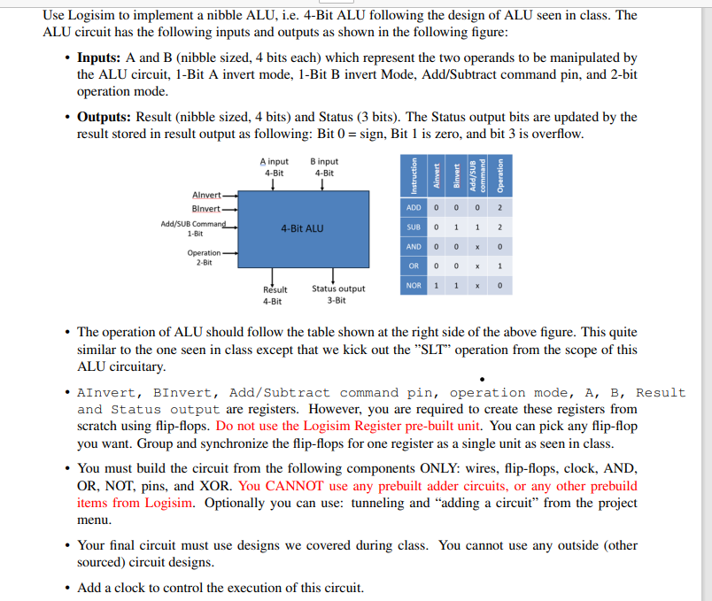
Use Logisim to implement a nibble ALU, i.e. 4-Bit ALU following the design of ALU seen in class. The ALU circuit has the following inputs and outputs as shown in the following figure: Inputs: A and B (nibble sized, 4 bits each) which represent the two operands to be manipulated by the ALU circuit, 1-Bit A invert mode, 1-Bit B invert Mode, Add/Subtract command pin, and 2-bit operation mode. Outputs: Result (nibble sized, 4 bits) and Status (3 bits). The Status output bits are updated by the result stored in result output as following: Bit 0 = sign, Bit 1 is zero, and bit 3 is overflow. Alnvert- Binvert Add/SUB Command 1-Bit Operation 2-Bit A input 4-Bit B input 4-Bit 4-Bit ALU Result 4-Bit Status output 3-Bit Instruction ADD Ainvert Binvert 1 0 0 0 an/pv 0 command SUB 0 AND 0 OR NOR 1 1 x 00 1 x Operation 2 2 0 x 1 0 The operation of ALU should follow the table shown at the right side of the above figure. This quite similar to the one seen in class except that we kick out the "SLT" operation from the scope of this ALU circuitary. AInvert, BInvert, Add/Subtract command pin, operation mode, A, B, Result and Status output are registers. However, you are required to create these registers from scratch using flip-flops. Do not use the Logisim Register pre-built unit. You can pick any flip-flop you want. Group and synchronize the flip-flops for one register as a single unit as seen in class. You must build the circuit from the following components ONLY: wires, flip-flops, clock, AND, OR, NOT, pins, and XOR. You CANNOT use any prebuilt adder circuits, or any other prebuild items from Logisim. Optionally you can use: tunneling and "adding a circuit" from the project menu. Your final circuit must use designs we covered during class. You cannot use any outside (other sourced) circuit designs. Add a clock to control the execution of this circuit.
Step by Step Solution
3.45 Rating (158 Votes )
There are 3 Steps involved in it
Step: 1
Step 1 Designing the 4Bit ALU in Logisim We will walk you through each step of creating a 4bit ALU in Logisim using the specified requirements 1Input ...
See step-by-step solutions with expert insights and AI powered tools for academic success
Step: 2

Step: 3

Ace Your Homework with AI
Get the answers you need in no time with our AI-driven, step-by-step assistance
Get Started


