Use logism Answer question 3
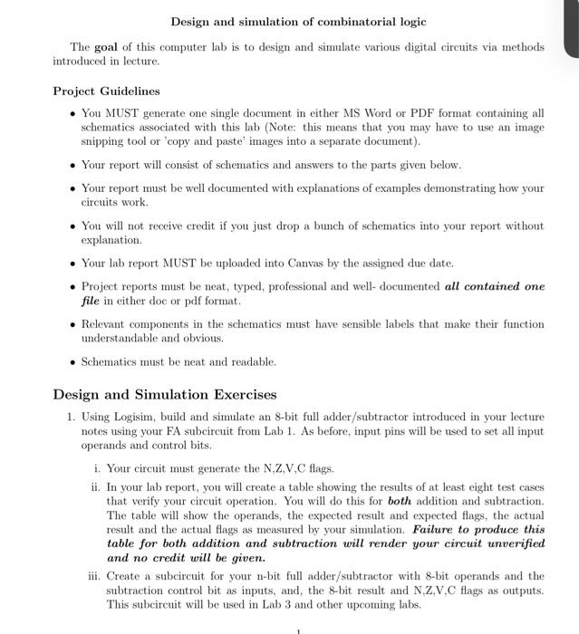
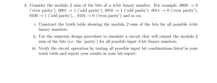
Design and simulation of combinatorial logic The goal of this computer lab is to design and simulate various digital circuits via methods introduced in lecture. Project Guidelines You MUST generate one single document in either MS Word or PDF format containing all schematics associated with this lab (Note: this means that you may have to use an image snipping tool or 'copy and paste images into a separate document). Your report will consist of schematics and answers to the parts given below. Your report must be well documented with explanations of examples demonstrating how your circuits work. You will not receive credit if you just drop a bunch of schematics into your report without explanation. . Your lab report MUST be uploaded into Canvas by the assigned due date. Project reports must be neat, typed, professional and well-documented all contained one file in cither doc or pdf format. Relevant components in the schematics must have sensible labels that make their function understandable and obvious. Schematics must be neat and readable. Design and Simulation Exercises 1. Using Logisim, build and simulate an 8-bit full adder/subtractor introduced in your lecture notes using your FA subcircuit from Lab 1. As before, input pins will be used to set all input operands and control bits. i. Your circuit must generate the N.Z.V.C flags. ii. In your lab report, you will create a table showing the results of at least eight test cases that verify your circuit operation. You will do this for both addition and subtraction. The table will show the operands, the expected result and expected flags, the actual result and the actual flags as measured by your simulation. Failure to produce this table for both addition and subtraction will render your circuit unverified and no credit will be given. iii. Create a subcircuit for your n-bit full adder/subtractor with 8-bit operands and the subtraction control bit as inputs, and, the 8-bit result and N.Z.V.C flags as outputs. This subcircuit will be used in Lab 3 and other upcoming labs. 3. Consider the modulo 2 sum of the bits of a 4-bit binary number. For example, 0000 0 ('even parity'), 0001 + 1 (odd parity'), 0010 1 (odd parity'), 0011 + 0 ('even parity'), 0100 1 ('odd parity'), , 0101 + 0 ('even parity') and so on. i. Construct the truth table showing the modulo 2 sum of the bits for all possible 4-bit binary numbers. ii. Use the minterm design procedure to simulate a circuit that will output the modulo 2 sum of the bits (i.e. the 'parity) for all possible input 4-bit binary numbers. iii. Verify the circuit operation by testing all possible input bit combinations listed in your truth table and report your results in your lab report