Answered step by step
Verified Expert Solution
Question
1 Approved Answer
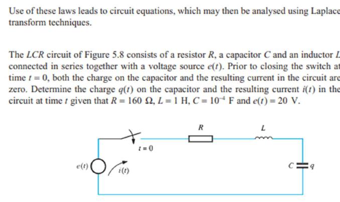
Use of these laws leads to circuit equations, which may then be analysed using Laplace transform techniques. The LCR circuit of Figure 5.8 consists

Use of these laws leads to circuit equations, which may then be analysed using Laplace transform techniques. The LCR circuit of Figure 5.8 consists of a resistor R, a capacitor C and an inductor L connected in series together with a voltage source e(t). Prior to closing the switch at time = 0, both the charge on the capacitor and the resulting current in the circuit are zero. Determine the charge q(t) on the capacitor and the resulting current i(t) in the circuit at time given that R = 160 2, L= 1 H, C=10 F and e(t) = 20 V. i(t) 1=0 R L m C=9
Step by Step Solution
There are 3 Steps involved in it
Step: 1
The detailed ...
Get Instant Access to Expert-Tailored Solutions
See step-by-step solutions with expert insights and AI powered tools for academic success
Step: 2

Step: 3

Ace Your Homework with AI
Get the answers you need in no time with our AI-driven, step-by-step assistance
Get Started


