

Answered step by step
Verified Expert Solution
Question
1 Approved Answer
use python Write the code using python. Write code in python. PROGRAM & TEST: Write a CircuitPython program that accomplishes the following: o Upon start-up,
use python
Write the code using python.
Write code in python.
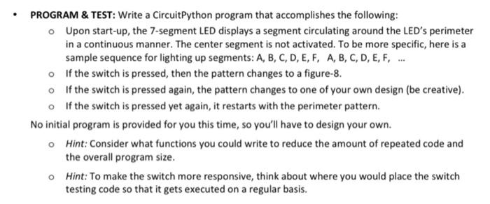
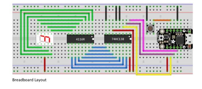
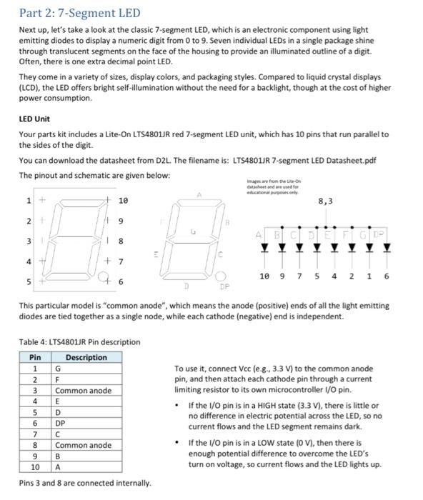
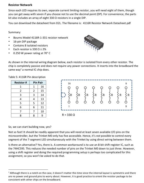
PROGRAM & TEST: Write a CircuitPython program that accomplishes the following: o Upon start-up, the 7-segment LED displays a segment circulating around the LED's perimeter in a continuous manner. The center segment is not activated. To be more specific, here is a sample sequence for lighting up segments: A, B, C, D, E, F, A, B, C, D, E, F, ... of the switch is pressed, then the pattern changes to a figure-8. o If the switch is pressed again, the pattern changes to one of your own design (be creative). o If the switch is pressed yet again, it restarts with the perimeter pattern. No initial program is provided for you this time, so you'll have to design your own. Hint: Consider what functions you could write to reduce the amount of repeated code and the overall program size. o Hint: To make the switch more responsive, think about where you would place the switch testing code so that it gets executed on a regular basis. 4116R 74HC138 Breadboard Layout Part 2: 7-Segment LED Next up, let's take a look at the classic 7-segment LED, which is an electronic component using light emitting diodes to display a numeric digit from 0 to 9. Seven individual LEDs in a single package shine through translucent segments on the face of the housing to provide an illuminated outline of a digit. Often, there is one extra decimal point LED. They come in a variety of sizes, display colors, and packaging styles. Compared to liquid crystal displays (LCD), the LED offers bright self-illumination without the need for a backlight, though at the cost of higher power consumption LED Unit Your parts kit includes a Lite-On LTS4801JR red 7-segment LED unit, which has 10 pins that run parallel to the sides of the digit. You can download the datasheet from D2L. The filename is: LT54801JR 7-segment LED Datasheet.pdf The pinout and schematic are given below: were from the item educational Post 1 + 10 8,3 dan weed for N 11 9 A B C D 1 8 4 + 7 10 9 7 5 4 2 1 6 un This particular model is "common anode", which means the anode (positive) ends of all the light emitting diodes are tied together as a single node, while each cathode (negative) end is independent. WN Table 4: LTS4801JR Pin description Pin Description 1 G 2 F 3 Common anode 4 E 5 D 6 DP 7 8 Common anode 9 B 10 A Pins 3 and 8 are connected internally. To use it, connect Vec (e.g., 3.3 V) to the common anode pin, and then attach each cathode pin through a current limiting resistor to its own microcontroller 1/0 pin. . If the I/O pin is in a HIGH state (3.3V), there is little or no difference in electric potential across the LED, so no current flows and the LED segment remains dark. If the I/O pin is in a LOW state (OV), then there is enough potential difference to overcome the LED's turn on voltage, so current flows and the LED lights up. Resistor Network Since each LED requires its own, separate current limiting resistor, you will need eight of them, though you can get away with seven if you choose not to use the decimal point (DP). For convenience, the parts kit also includes an array of eight 3300 resistors in a single DIP. You can download the datasheet from D2L. The filename is: 4116R Resistor Network Datasheet.pdf Summary: Bourns Model 4116R-1-331 resistor network 16-pin DIP package . Contains 8 isolated resistors Each resistor is 3300 + 2% 0.250 W power rating at 70C . As shown in the internal wiring diagram below, each resistor is isolated from every other resistor. The chip is completely passive and does not require any power connections. It inserts into the breadboard the same way' a normal IC chip does. Table 5: 4116R Pin description Resistor # Pin Pair 16 16 1 2 R 1 2 3 4 5 6 7 8 3 4 5 6 7 8 15 14 13 12 11 10 9 1 8 R = 3300 So, we can start building now, yes? Not so fast! It should be readily apparent that you will need at least seven available 1/0 pins on the microcontroller, but the Trinket MO only has five accessible. Hence, it's not possible to control every segment of the 7-segment LED simultaneously with the Trinket by using direct wiring between them. Is there an alternative? Yes, there is. A common workaround is to use an 8-bit shift register IC, such as the 74HC595. This reduces the needed number of pins on the Trinket Mo down to just three. However, using a shift register and doing the required programming setup is perhaps too complicated for this assignment, so you won't be asked to do that. Although there is a notch on the case, it doesn't matter this time since the internal layout is symmetric and there are no power and ground pins to worry about. However, it is good practice to orient the resistor package to be consistent with other chips on the breadboard Step by Step Solution
There are 3 Steps involved in it
Step: 1

Get Instant Access to Expert-Tailored Solutions
See step-by-step solutions with expert insights and AI powered tools for academic success
Step: 2

Step: 3
Ace Your Homework with AI
Get the answers you need in no time with our AI-driven, step-by-step assistance
Get Started
Database Driven Web Sites
Authors: Mike Morrison, Joline Morrison
1st Edition
061901556X, 978-0619015565