Question
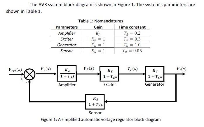
ANSWER FOR QUESTIONS C AND D USING MATHLAB. The AVR system block diagram is shown in Figure 1. The system's parameters are shown in Table


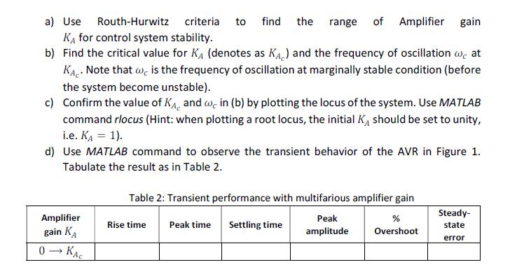
ANSWER FOR QUESTIONS C AND D USING MATHLAB.
The AVR system block diagram is shown in Figure 1. The system's parameters are shown in Table 1. Vref (S) Ve(s) Parameters Amplifier Exciter Generator Sensor KA 1+TAS Amplifier Table 1: Nomenclatures Gain KE = 1 KG = 1 KR = 1 VR(S) KE 1+TES Exciter KR 1+ TRS Time constant TA = 0.2 TE = 0.3 TG = 1.0 TR = 0.05 VF (S) KG 1+ TGS Generator Sensor Figure 1: A simplified automatic voltage regulator block diagram V,(s)
Step by Step Solution
3.58 Rating (155 Votes )
There are 3 Steps involved in it
Step: 1

Get Instant Access to Expert-Tailored Solutions
See step-by-step solutions with expert insights and AI powered tools for academic success
Step: 2

Step: 3

Ace Your Homework with AI
Get the answers you need in no time with our AI-driven, step-by-step assistance
Get StartedRecommended Textbook for
Elementary Statistics Picturing The World
Authors: Ron Larson, Betsy Farber
6th Edition
0321911210, 978-0321911216
Students also viewed these Physics questions
Question
Answered: 1 week ago
Question
Answered: 1 week ago
Question
Answered: 1 week ago
Question
Answered: 1 week ago
Question
Answered: 1 week ago
Question
Answered: 1 week ago
Question
Answered: 1 week ago
Question
Answered: 1 week ago
Question
Answered: 1 week ago
Question
Answered: 1 week ago
Question
Answered: 1 week ago
Question
Answered: 1 week ago
Question
Answered: 1 week ago
Question
Answered: 1 week ago
Question
Answered: 1 week ago
Question
Answered: 1 week ago
Question
Answered: 1 week ago
Question
Answered: 1 week ago
Question
Answered: 1 week ago
Question
Answered: 1 week ago
Question
Answered: 1 week ago
Question
Answered: 1 week ago
View Answer in SolutionInn App


