Answered step by step
Verified Expert Solution
Question
1 Approved Answer
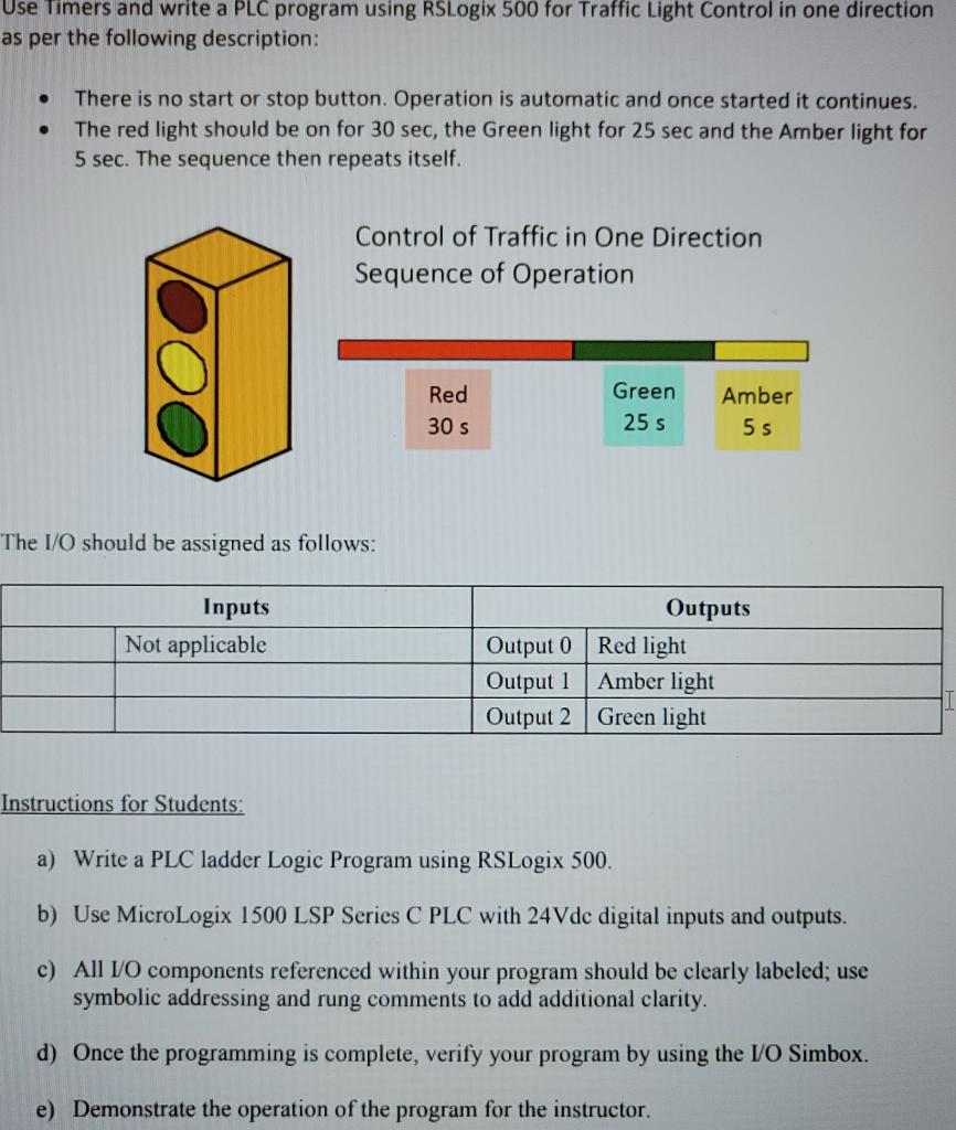
Use Timers and write a PLC program using RSLogix 500 for Traffic Light Control in one direction as per the following description: There is


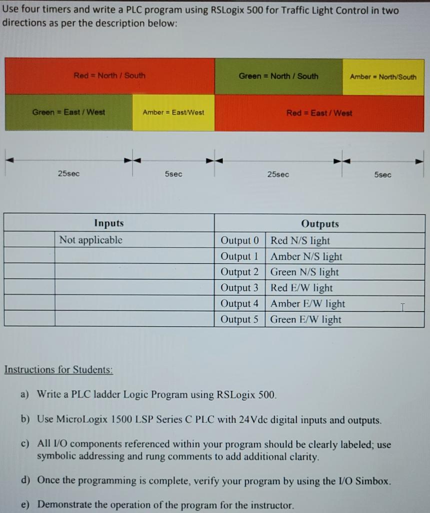
Use Timers and write a PLC program using RSLogix 500 for Traffic Light Control in one direction as per the following description: There is no start or stop button. Operation is automatic and once started it continues. The red light should be on for 30 sec, the Green light for 25 sec and the Amber light for 5 sec. The sequence then repeats itself. Control of Traffic in One Direction Sequence of Operation Red Green Amber 30 s 25 s 5 s The I/O should be assigned as follows: Inputs Outputs Output 0 Red light Output 1Amber light Green light Not applicable Output 2 Instructions for Students: a) Write a PLC ladder Logic Program using RSLogix 500. b) Use MicroLogix 1500 LSP Series C PLC with 24Vdc digital inputs and outputs. c) All /O components referenced within your program should be clearly labeled; use symbolic addressing and rung comments to add additional clarity. d) Once the programming is complete, verify your program by using the I/O Simbox. e) Demonstrate the operation of the program for the instructor. Use four timers and write a PLC program using RSLogix 500 for Traffic Light Control in two directions as per the description below: Red = North / South Green = North/South Amber = North/South Green = East/West Amber = East/West Red = East/West 25sec 5sec 25sec 5sec Inputs Outputs Not applicable Output 0 Red N/S light Amber N/S light Output 1 Output 2 Green N/S light Output 3 Output 4 Amber E/W light Output 5 Green E/W light Red E/W light Instructions for Students: a) Write a PLC ladder Logic Program using RSLogix 500. b) Use MicrolLogix 1500 LSP Series C PLC with 24 Vdc digital inputs and outputs. c) All 1/O components referenced within your program should be clearly labeled; use symbolic addressing and rung comments to add additional clarity. d) Once the programming is complete, verify your program by using the I/O Simbox. e) Demonstrate the operation of the program for the instructor.
Step by Step Solution
There are 3 Steps involved in it
Step: 1
Kal The given logic can be implement with the following ladder program in Rslo...
Get Instant Access to Expert-Tailored Solutions
See step-by-step solutions with expert insights and AI powered tools for academic success
Step: 2

Step: 3

Ace Your Homework with AI
Get the answers you need in no time with our AI-driven, step-by-step assistance
Get Started


