Using and changing the following codes togther
//CPWM.c // This program produces a ramp function on the PWM port bit P1.3. #include void Delay(int x); void main(void) {unsigned char pcaData; //data byte for the ramp function CKCON = 0x01; // x2 mode CMOD = 0x02; //Clock bit CPS1, CPS0 = 01 so PCA clock // is cpu clock/2 CCON = 0x40; //Bit 6 in CCON turns on PCA timer CCAPM0 = 0x42; //Bit 6 enables the compare mode for PWM // and bit 2 enables PWM while(1) {CCAP0H = pcaData; //Load data to high byte of capture register pcaData++; //Increment register for a ramp Delay(1); //Software delay for about 250 useconds } } void Delay(int x) {int i, j; for(i=0;i -----
//AtoDTest.c #include //Takes the input from the A/D converter channel 0 and // sends it to P2 and P3. Assumes P2 has D/A triggered // by bit P4.0. P2 holds 8 MSBs. void main (void) {unsigned char tmp; ADCF = 0x01; // P1.0 = ADC[0] ADCON = 0x20; // Enable ADC Function ADCLK = 0x00; // Prescaler to 0 EA = 0; //Turn off interrupts while(1) // Loop Forever {ADCON &= 0xF8; // Reset ADC Channel Select ADCON |= 0x00; // Select ADC = Ch0 ADCON |= 0x20; // Use Standard mode ADCON |= 0x08; // Start ADC Convert tmp = (ADCON & 0x10); // Get done bit while(tmp != 0x10) // Loop until complete tmp = (ADCON & 0x10); P2 = ADDH; // Send 8 MSB to P2 P3 = ADDL; P4_0 = 0; // Low going pulse to D to A P4_0 = 1; // write line ADCON &= 0xEF; // Clear ADEOC = 0 }
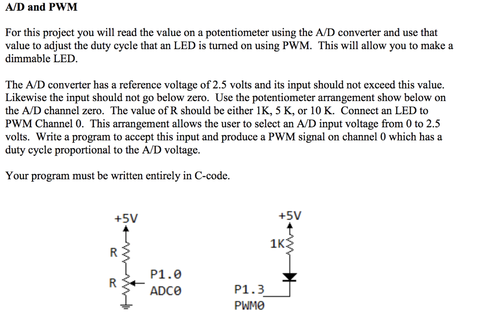
A/D and PWM For this project you will read the value on a potentiometer using the A/D converter and use that value to adjust the duty cycle that an LED is turned on using PWM. This will allow you to make a dimmable LED. The A/D converter has a reference voltage of 2.5 volts and its input should not exceed this value. Likewise the input should not go below zero. Use the potentiometer arrangement show below on the A/D channel zero. The value of R should be either 1K, 5 K, or 10 K. Connect an LED to PWM Channel 0. This arrangement allows the user to select an A/D input voltage from 0 to 2.5 volts. Write a program to accept this input and produce a PWM signal on channel 0 which has a duty cycle proportional to the A/D voltage. Your program must be written entirely in C-code. +5V +5V 1K P1.0 ADCe P1.3 PWMO A/D and PWM For this project you will read the value on a potentiometer using the A/D converter and use that value to adjust the duty cycle that an LED is turned on using PWM. This will allow you to make a dimmable LED. The A/D converter has a reference voltage of 2.5 volts and its input should not exceed this value. Likewise the input should not go below zero. Use the potentiometer arrangement show below on the A/D channel zero. The value of R should be either 1K, 5 K, or 10 K. Connect an LED to PWM Channel 0. This arrangement allows the user to select an A/D input voltage from 0 to 2.5 volts. Write a program to accept this input and produce a PWM signal on channel 0 which has a duty cycle proportional to the A/D voltage. Your program must be written entirely in C-code. +5V +5V 1K P1.0 ADCe P1.3 PWMO