Answered step by step
Verified Expert Solution
Link Copied!

Question

1 Approved Answer

Using Logisim implement the following circuit. The outputs of four registers, RO, R1, R2 and R3 are connected through 4-1 Mux to the input of
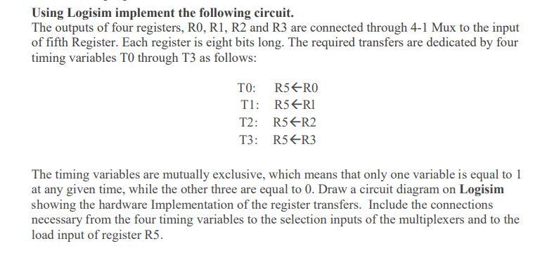
image text in transcribed

Using Logisim implement the following circuit. The outputs of four registers, RO, R1, R2 and R3 are connected through 4-1 Mux to the input of fifth Register. Each register is eight bits long. The required transfers are dedicated by four timing variables TO through T3 as follows: TO: R5RO T1: R5ERI T2: R5R2 T3: R5ER3 The timing variables are mutually exclusive, which means that only one variable is equal to 1 at any given time, while the other three are equal to 0. Draw a circuit diagram on Logisim showing the hardware Implementation of the register transfers. Include the connections necessary from the four timing variables to the selection inputs of the multiplexers and to the load input of register R5

Step by Step Solution

There are 3 Steps involved in it

Step: 1

blur-text-image

Get Instant Access to Expert-Tailored Solutions

See step-by-step solutions with expert insights and AI powered tools for academic success

Step: 2

blur-text-image_2

Step: 3

blur-text-image_3

Ace Your Homework with AI

Get the answers you need in no time with our AI-driven, step-by-step assistance

Get Started

Recommended Textbook for

Records And Database Management

Authors: Jeffrey R Stewart Ed D, Judith S Greene, Judith A Hickey

4th Edition

0070614741, 9780070614741

More Books

Students also viewed these Databases questions

Question

How does international marketing differ from domestic marketing?

Answered: 1 week ago

Question

05 Techniques to promote creativity and in novation.

Answered: 1 week ago

Question

What are the Five Phases of SDLC? Explain each briefly.

Answered: 1 week ago

Question

How can Change Control Procedures manage Project Creep?

Answered: 1 week ago