Question
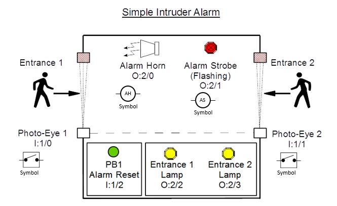
Using Rs Logix Pro Design the following circuit: Initial Conditions: Alarm horn (AH), Alarm strobe (AS), Entrance 1 lamp (LP1) and Entrance 2 lamp (LP2)
Using Rs Logix Pro Design the following circuit:
Initial Conditions: Alarm horn (AH), Alarm strobe (AS), Entrance 1 lamp (LP1) and Entrance 2 lamp (LP2) are all OFF. Entrance 1 photo-eye sensor (PE1) and Entrance 2 photo-eye sensor (PE2)are OPEN when unblocked and only changes to CLOSE if someone is blocking the beam (i.e. when someone enters).
If someone enters the room at Entrance 1, the Alarm Horn, Alarm strobe, and Entrance 1 lamp are enabled and stay ON until the Alarm Reset push button (PB1) is pressed. If someone enters the room at Entrance 2, the Alarm Horn, Alarm strobe, and Entrance 2 lamp are enabled and stay ON until the Alarm Reset push button (PB1) is pressed.
NOTE: The Alarm strobe light flashes at a clock rate of 1.28 seconds.
a.You are required to design, test, and submit a ladder logic program and I/O connection
diagram for this system.
Notes:
PB1 (Alarm Reset) is a momentary, normally open, push button
Entrance 1 and Entrance 2 Photo-eye sensors are normally open sensors

Entrance 1 8 Photo-Eye 1 1:1/0 Symbol Simple Intruder Alarm Alarm Horn. Alarm Strobe O:2/0 (Flashing) 0:2/1 AS Symbol AH Symbol PB1 Alarm Reset 1:1/2 Entrance 1 Lamp O:2/2 Entrance 2 Lamp O:2/3 Entrance 2 - Photo-Eye 2 1:1/1 Symbol
Step by Step Solution
There are 3 Steps involved in it
Step: 1
THE PLC LADDER DIAGR...
Get Instant Access to Expert-Tailored Solutions
See step-by-step solutions with expert insights and AI powered tools for academic success
Step: 2

Step: 3

Ace Your Homework with AI
Get the answers you need in no time with our AI-driven, step-by-step assistance
Get Started


