Answered step by step
Verified Expert Solution
Question
1 Approved Answer
Using the pipework isometric drawing in Figure 6, list the number of welds of each type and size required; create a list of cut
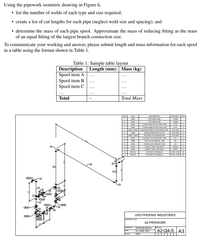
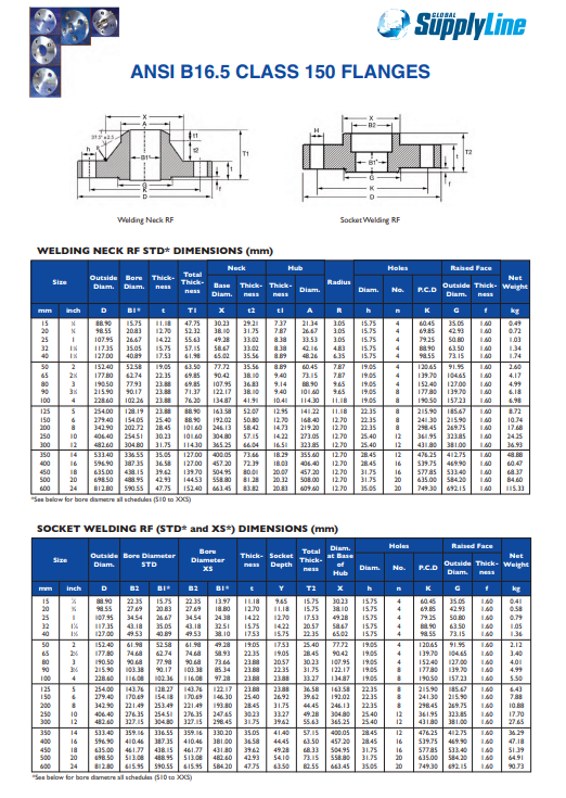
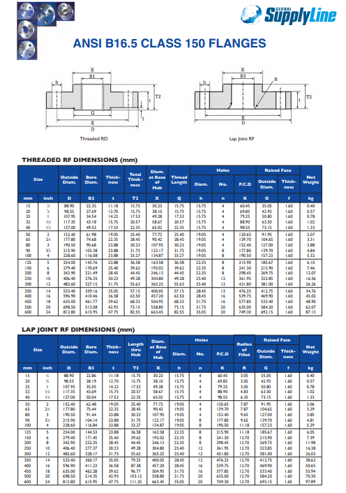
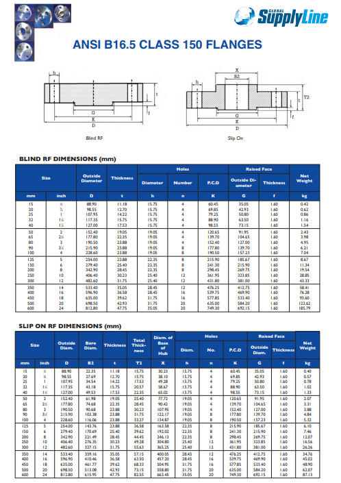
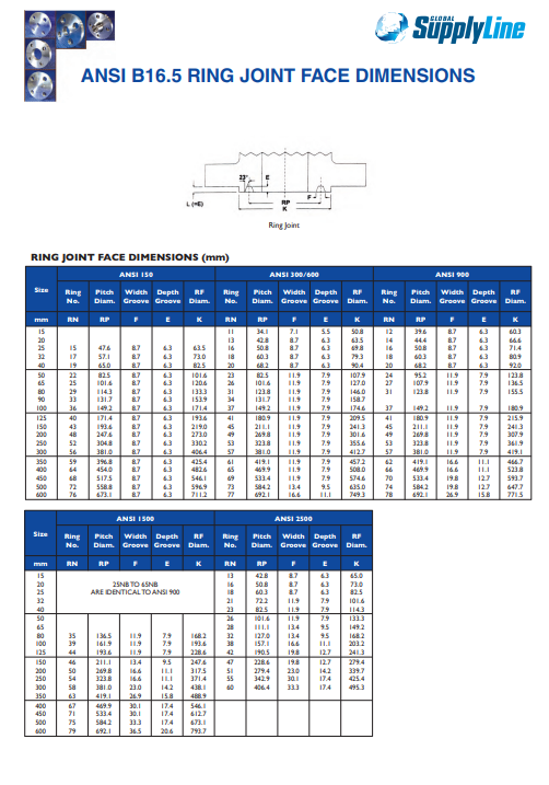
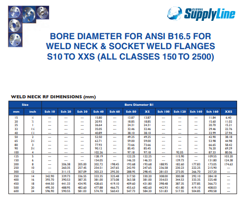
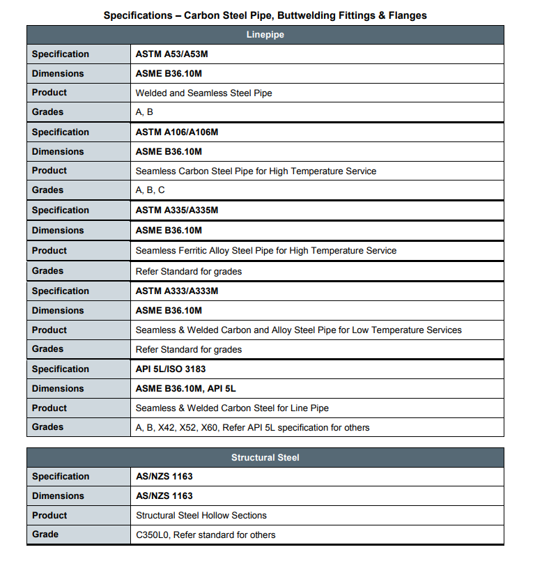
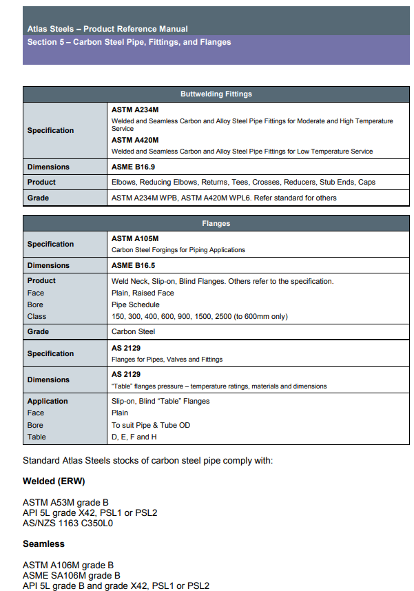
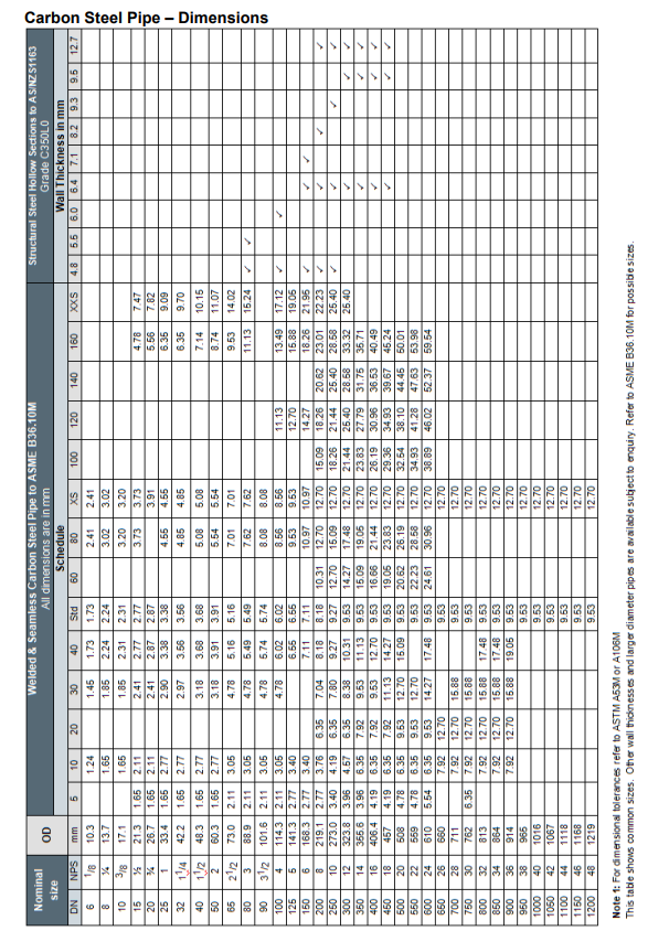
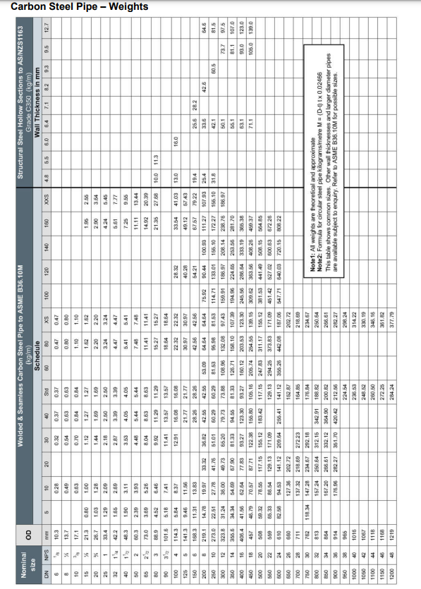
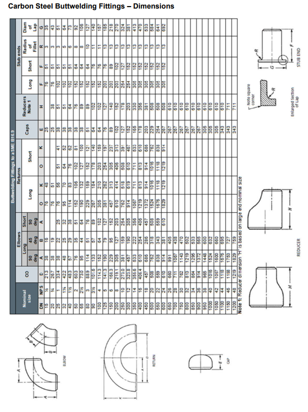
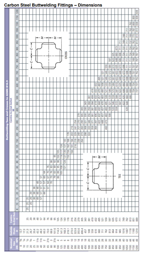
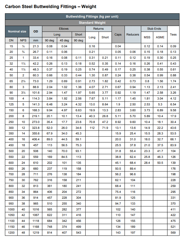
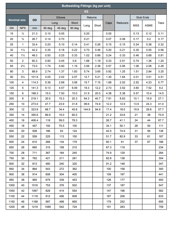
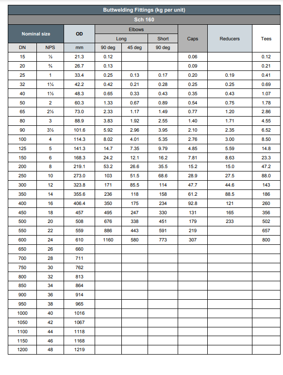
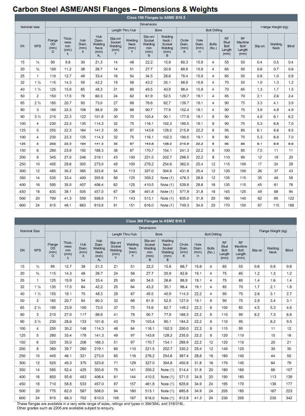
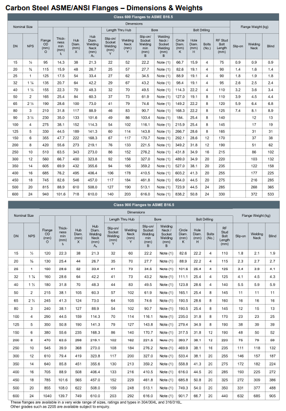
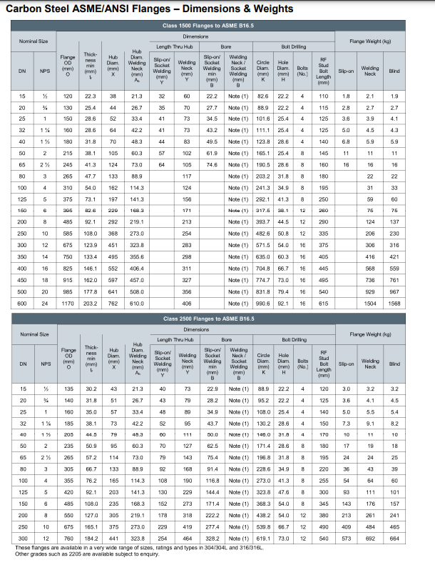
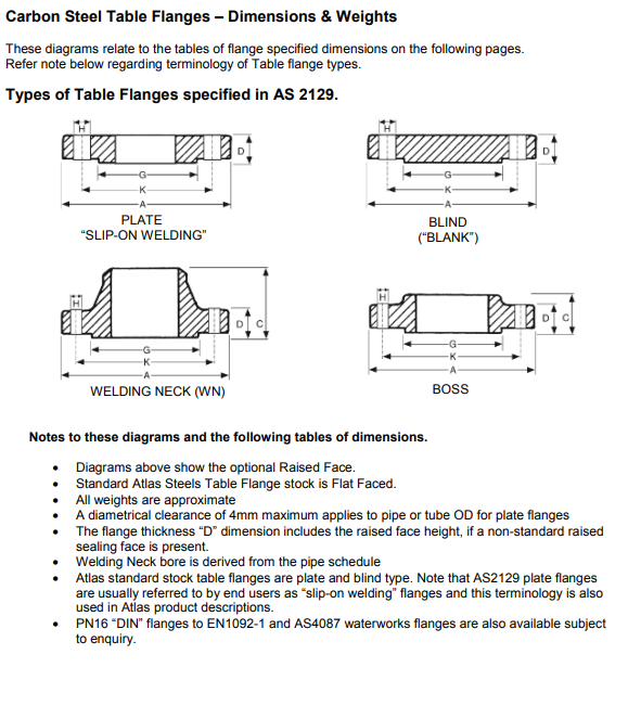
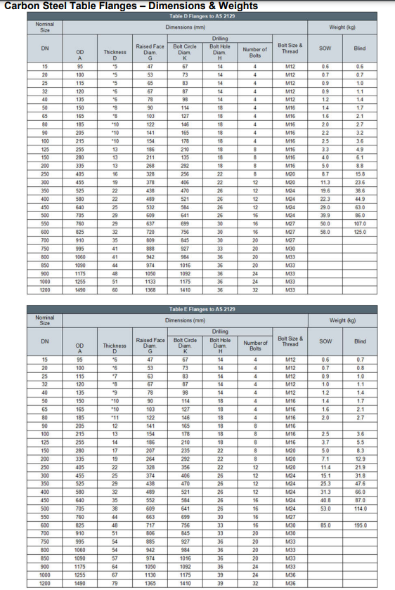
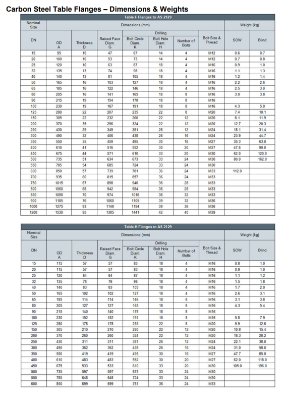
Using the pipework isometric drawing in Figure 6, list the number of welds of each type and size required; create a list of cut lengths for each pipe (neglect weld size and spacing); and determine the mass of each pipe spool. Approximate the mass of reducing fitting as the mass of an equal fitting of the largest branch connection size. To communicate your working and answer, please submit length and mass information for each spool in a table using the format shown in Table 1. 000 Table 1: Sample table layout Description Spool item A Spool item B Spool item C Total Length (mm) Mass (kg) 9 Total Mass 7 11 14 SIZE ONSD ONID DINGO DINID DENSO ONID DENSO DINGO ONSD DINSO OND M16x20 M16x75 DRAWING TITLE SPAINN BY SATE SCALE DESCRIPTION PIPE ONSD PIPE DN FLANGEONSORF WN FLANGE DNRF WN REDUCER DIN50 CONCENTRIC ELBOW DNI SEDEG LR DW TEE REDUCING DOW CONTROL VALVEONSORF 150 GATE VALVE DNI RF 150# GLOSE VALVE ONSORF 150# GASKET ONS SPWD GASKET ONIO 150# SPIND STUD BOLT MI STUD BOLT M 150# 150# A2-PIPEWORK BYRENN BIRCH 07 JUNE 2023 NTS MATERIAL OTY A1000 A1000 USQ PHOENIX INDUSTRIES A105 A234 WP A234 WPB A234 WPG CS 30455 20455 A3/A4 A3/A4 S 16 A2-Q4-S A3 TIT mm 15 20 25 40 50 65 WELDING NECK RF STD* DIMENSIONS (mm) Outside Bore Thick. Total Diam. Diam. ness Thick- ness 90 100 125 150 200 250 300 15 40 50 350 16 400 450 18 20 500 600 65 90 Size 1:00 125 150 inch % "See below for bore diametre all schedules (50 to XXS) 250 300 350 IN 18 2 2x 3 38 Size 450 500 600 3 8 10 12 SOCKET WELDING RF (STD* and XS*) DIMENSIONS (mm) Thick Socket Total Diam ness Depth ness at Base Thick- Hub inch xx-2 1% ANSI B16.5 CLASS 150 FLANGES Welding Neck RF 10 12 88.90 117.35 1% 127.00 Outside Bore Diameter Diam. STD 82 22.35 27.69 107.95 34.54 18.55 t BI* 15.35 20 83 26.67 43.18 35.05 49.53 40.89 52.58 152.40 61.98 x tl A 21.34 3.05 15.75 26.67 3.05 15.75 33.53 3.05 15.75 42.16 483 15.75 4.35 15.75 63.50 11.22 35.56 8.89 7.87 90.42 TI 86.90 15.75 47.75 30.23 29.21 7.37 98.55 20.83 12.70 52.32 38.10 31.75 7.87 107.95 26.67 14.22 55.63 49.28 33.02 8.38 117.35 35.05 15.75 57.15 58.67 33.02 8.38 127.00 40.89 17.53 61.98 65.00 35.56 8.89 48.26 152.40 52.58 60.45 19.05 177.80 22.35 18.10 73.15 7.87 19.05 190.50 77.93 23.88 69.85 107.95 36.83 9.14 88.90 9.65 19.05 215.90 90.17 23.88 71.37 122.17 38.10 101.60 9.65 19.05 228.60 102.26 23.88 76.20 134.87 41.91 10.41 11.18 19.05 8 254.00 128.19 23.88 88.90 163.58 52.07 12.95 141.22 11.18 279.40 154.05 25.40 88.90 192.02 50.80 12.30 168.40 12.70 22.35 342.90 202.72 28.45 101.60 246.13 58.42 14.73 219.20 12.70 22.35 235 406.40 254.51 30.23 101.60 304.80 57.15 14.22 273.05 12.70 25.40 482.60 304.80 31.75 114.30 345.25 66.04 16.51 323.85 12.70 25.40 18:29 127.00 35.05 400.05 73.66 18.29 355.60 28.45 12 127.00 72.39 18.03 406.40 12.70 28.45 16 80.01 20.07 457.20 12.70 31.75 16 20.32 508.00 12.70 31.75 20 20.83 609.60 12.70 35.05 20 336.55 12.30 531.40 336.55 596.90 387.35 36.58 635.00 438.15 39.42 139.70 698.50 488.95 42.93 14453 558.80 81.28 812.80 590.55 47.75 152.40 663.45 T1 Diameter xs Neck Hub Base Thick- Thick- Diam. ness 77.98 90.17 103.38 102.36 116.08 "See below for bore diametre all schedules ($10 to XXS) 177.80 74.68 190.50 90.48 215.90 103.36 228.60 116.08 254.00 143.76 279.40 170.69 342.90 221.49 128.27 143.76 154.18 170.69 253.49 221.49 298.45 31.75 3962 406.40 276.35 254.51 276.35 247.45 30.23 33.27 482.60 327.15 304.80 327.15 359.16 336.55 359.16 330.20 35.05 410.46 387.35 410.46 381.00 36.58 44.45 18 635.00 461.27 438.15 461.77 431.80 3962 49.28 698.50 513.08 488.95 513.08 482.60 42.93 54.10 24 812.80 415.95 590.55 615.95 584.20 47.35 63.50 16 596.90 20 Diam. Socket Welding RF Radius 82 BI* T2 22.35 Y 13.97 11.18 9.65 15.75 12.70 11.18 15.75 34.54 24.38 1422 12.70 17.53 32.51 15.35 27.69 43.18 49.53 38.10 61.98 17.53 19.05 22.35 17.53 25.40 19.05 19.05 19.05 74.68 58.93 28.45 90.42 19.05 90.68 73.66 23.88 20.57 30.23 107.95 19.05 85.34 2388 22.35 31.75 122.17 97.28 23.00 23.88 33.27 134.87 122.17 23.88 23.88 36.58 163.58 22.35 146.30 25.40 26.92 192.02 22.35 193.80 28:45 31.75 44.45 246.13 22.35 49.28 304.80 25.40 55.43 365.25 25.40 400.05 63.50 457.20 28.45 (33 504.95 31.75 73.15 558.80 31.75 82.55 643.45 35.05 41.40 Diam. 1422 20.57 58.67 15.75 15.75 22.35 65.02 15.75 Holes 15.75 30.23 38.10 15.75 49.28 15.75 No. ***** 4 8 8 Supply Line P.C.D 44488.88 85 Raised Face 8 Net Outside Thick Weight Diam. 60.45 35.05 1.40 69.85 42.93 1.40 79.25 50.80 1.60 88.90 98.55 120.45 91.95 1.60 139.70 10465 1.60 152.40 127.00 1.60 177.80 139.70 1.60 190.50 157.23 1.60 215.90 185.67 1.60 241.30 215.90 1.60 298.45 249.75 1.60 361.95 323.85 1.40 12 431.80 381.00 1.40 476.25 412.75 1.60 539.75 1.60 577.85 533.40 1.60 635.00 584.20 1.60 749.30 692.15 1.60 63.50 1.60 73.15 1.40 kg 0.49 0.72 1.03 1.34 1.74 Holes Raised Face Net Diam. No. P.C.D Outside Thick- Weight Diam. ness 2.60 4.17 4.99 6.18 6.98 8.72 10.34 17.68 24.25 36.93 48.88 68.37 84.60 115.33 4 60.45 35.05 1.60 69.85 1.60 50.80 1.60 63.50 1.60 73.15 1.60 1.60 2.12 1.40 4 79.25 4 98.55 120.45 91.95 104.45 139.70 152.40 127.00 177.80 139.70 190.50 157.23 1.60 215.90 185.67 1.60 241.30 215.90 1.60 7.88 298.45 269.75 1.60 10.88 17.30 27.65 1.60 4.01 1.60 4.99 5.50 361.95 323.85 1.60 431.80 381.00 1.60 476.25 1.40 36.29 539.75 469.90 1.60 47.18 16 577.85 533.40 1.60 $1.39 20 635.00 584.20 1.60 64.91 20 749.30 492.15 1.60 90.33 12 16 kg 0.58 0.79 1.05 1.36 ********** 125 150 200 300 THREADED RF DIMENSIONS (mm) Total Thick- 350 400 450 500 600 mm - 1 3 Size 500 inch Size % I 1% 1% 2 a 3 306 4 5 . 10 12 16 18 20 inch ON 2 2% 4 5 : ANSI B16.5 CLASS 150 FLANGES 10 12 D 88.90 98.55 107.95 Outside Bore Thick- Diam. Diam. 117.35 127.00 152.40 215.90 228.60 B1 1% 117.35 1% 127.00 Threaded RD 61.98 177.80 74.68 190.50 B2 22.35 27.49 152.40 177.80 34.54 43.18 49.53 190.50 215.90 228.60 406.40 482.60 533.45 533.40 596.90 19.05 22.35 90.48 23.88 103.38 116.08 LAP JOINT RF DIMENSIONS (mm) Outside Bore Thick Langeh Diam. Diam. ness D 88.90 22.86 98.55 28.19 107.95 35.05 11.18 12.70 14.22 15.75 17.53 143.76 23.88 170.69 23.08 23.88 254.00 279.40 342.90 406.40 276.35 30.23 49.28 482.60 327.15 31.75 55.63 50.04 62.48 75.44 116.84 254.00 144.53 279.40 171.45 342.90 222.25 25.40 28.45 t 11.18 12.70 14.22 15.75 17.53 T2 15.75 15.75 17.53 20.57 22.35 23.88 25.40 28.45 533.40 359.16 35.05 57.15 400.05 57.15 596.90 410.46 36.58 63.50 457.20 63.50 635.00 461.77 39.62 68.33 50495 68.33 698.50 513.08 42.93 73.15 558.80 73.15 812.80 615.95 47.75 80.55 663.45 82.55 277.37 30.23 338.17 31.75 360.17 35.05 16 36.58 3942 18 635.00 462.28 20 698.50 514.35 812.80 615.95 47.75 42.93 24 25.40 28.45 30:23 107.95 Diam. at Base of Hub thru Hub X 30.23 38.10 49.28 58.67 65.02 77.72 T3 15.75 15.75 17.53 20.57 31.75 122.17 31.75 33.27 13487 33.27 36.58 163.58 36.58 39.62 19202 44.45 246.13 44.45 30480 365.25 55.43 Diam. at Base x 30.23 38.10 49.28 58.47 22.35 45.00 19.05 22.35 28.45 90.42 23.88 30.23 23.88 23.86 79.25 67.38 Thread Length Diam of Hub Q 15.75 15.75 17.53 20.57 22.35 25.40 28.45 30.23 Diam. 25.40 77.72 19.05 19.05 107.95 19.05 122.17 19.05 31.75 33.27 134.87 19.05 15.75 15.75 15.75 15.75 15.75 36.58 163.58 22.35 39.42 192.02 22.35 44.45 246.13 22.35 49.28 55.43 304.80 25.40 345.25 T 25.40 28.45 18.45 31.75 457.20 504.95 103.12 558.80 31.75 111.25 663.45 35.05 15.35 15.75 15.35 15.35 15.35 19:05 19:05 19:05 19:05 19.05 22.35 22.35 22.35 25.40 25.40 28.45 28.45 31.35 31.75 35.05 Holes No. 4 4 A 4 4 4 ----222222 8 8 12 12 16 16 20 20 Holes No. 4 4 4 4 4 A 8 8 Lap Joint RF 83 P.C.D K 60.45 69.85 79.25 88.90 98.55 P.C.D K 60.45 69.85 79.25 88.90 98.55 120.45 139.70 152.40 12 12 16 16 20 435.00 20 SupplyLine 139.70 177.30 190.50 157.23 8 8 8 298.45 269.75 12 361.95 323.85 431.80 381.00 476.25 412.75 539.75 577.85 533.40 584.20 749.30 692.15 Radius of Fillet 12.30 12 476.25 539.75 12.30 577.85 12.30 635.00 749.30 12.30 12.30 3.05 3.05 4.83 6.35 Raised Face Outside Thick- Diam. ness 120.45 7.87 139.70 7.87 152.40 177.80 9.65 190.50 IL18 42.93 50.80 63.50 73.15 91.95 104.45 127.00 215.90 185.67 1.40 241.30 215.90 1.60 35.05 42.93 50.80 4 1.60 1.60 1.60 215.90 11.18 341.30 12.30 215.90 298.45 12.70 269.75 361.95 431.80 12.30 323.85 12.30 381.00 1.60 1.40 1.60 1.60 1.60 533.40 584.20 692.15 1.60 1.60 1.60 1.60 1.60 1.60 1.60 1.60 1.60 1.60 73.15 1.60 91.95 1.40 10465 1.60 127.00 1.60 139.70 1.40 157.23 f Raised Face Net Outside Thick- Weight Diam. 1.60 1.60 1.60 1.60 Net Weight 1.40 1.40 1.60 1.60 1.60 kg 0.40 0.57 0.78 1.02 1.33 2.07 3.88 4.84 5.32 6.10 7.46 12.07 26.26 34.76 45.00 48.90 87.13 0.40 0.57 0.78 1.02 1.33 2.06 3.29 ** 3.85 ** 4.81 5.29 6.05 7.39 11.98 26.03 26.03 1843 50.65 55.94 70.30 97.89 RA38888888 BLIND RF DIMENSIONS (mm) 25 100 65 125 150 200 250 300 350 400 500 600 40 mm 15 100 125 150 200 250 300 350 Size 450 500 600 inch X N ------ 1% 26 an 4 8 Inch 10 12 **-- % 136 1% 2 26 3 308 5 8 10 12 16 18 20 24 ANSI B16.5 CLASS 150 FLANGES D 88.90 98.55 107.95 306 215.90 238.60 117.35 127.00 SLIP ON RF DIMENSIONS (mm) 152.40 177.80 190.50 254.00 K D 279.40 Blind RF 342.90 406.40 48260 Outside Diameter D 88.90 98.55 107.95 117.35 127.00 Outside Bore Diam. Diam. 152.40 177.80 190.50 215.90 238.60 254.00 279.40 342.90 406.40 482.60 533.40 596.90 435.00 698.50 812.80 82 22.35 27.69 34.54 43.18 49.53 74.68 90.68 103.38 116.06 143.76 170.69 221.49 276.35 327.15 533.40 596.90 18 435.00 20 498.50 513.08 24 81280 615.95 359.16 410.46 461.37 Thickness 11.18 12.30 15.35 17.53 19:05 22.35 23.88 23.88 23.88 23.88 25.40 28.45 30.23 31.75 35.05 36.58 42.93 47.35 t 11.18 12.70 1422 Total Thickness Thick- 15.75 17.53 19.05 22.35 23.88 23.88 23.88 25.40 28.45 30.23 31.75 35.05 36.58 Diameter 39.43 42.93 47.75 T2 15.75 15.75 1251 20.57 22.35 25.40 28.45 30.23 31.75 36.58 39.62 4445 49.28 55.63 15.75 15.75 15.75 73.15 82.55 15.75 15.75 19.05 19.05 19.05 19.05 22.35 22.35 22.35 25,40 25,40 28.45 28.45 31.75 31.75 35.05 Diam. of Base of Hub x 30.23 38.10 49.28 45.02 77.32 90.42 107.95 122.17 134.87 246.13 304.80 365.25 57.15 400.05 63.50 457.20 504.95 Holes Number 558.80 663.45 4 4 4 * 8 885555. 12 12 16 16 20 20 Diam. 15.35 15.75 15X 15.75 15.35 19:05 163.58 22.35 192.02 22.35 19:05 19:05 19.05 19:05 22.35 25.40 25.40 28.45 31.75 31.75 35.05 P.C.D 40.45 69.85 79.25 88.90 98.55 120.65 139.30 152.40 177.80 190.50 215.90 241.30 298.45 361.95 431.80 476.25 5.39.75 577.85 635.00 749.30 Holes No. 4 4 4 4 B 8 8 8 12 12 12 16 16 20 20 B2 K D Slip On Outside Di- ameter 35.05 42.93 50.80 63.50 73.15 91.95 104.65 127.00 139.70 157.23 185.67 215.90 269.75 Raised Face 323.85 381.00 412.75 469.90 533.40 584.20 692.15 P.C.D K 60.45 69.85 79.25 88.90 98.55 SupplyLine 298.45 361.95 431.80 Thickness 476.25 539.75 577.85 635.00 749.30 120.65 91.95 139.70 104.65 35.05 42.93 50.80 43.50 78.15 152.40 127.00 177.80 139.70 157:23 190.50 215.90 185.67 241.30 215.90 Raised Face f 1.40 1.40 1.60 1.60 1.60 269.75 323.85 381.00 412.75 1.40 1.60 1.60 1.40 1.40 533.40 584.20 692.15 1.40 1.60 1.60 1.40 1.40 1.60 1.60 1.60 1.60 1.60 1.60 Net Outside Thickness Weight Diam. 1.60 1.60 1.60 1.60 1.60 1.60 1.60 1.60 1.60 1.60 1.40 1.40 T2 1.60 1.60 1.60 1.60 1.40 Net Weight 0.42 0.62 0.86 1.16 1.54 2.43 3.98 4.95 621 7.04 11.34 19.54 28.85 43.33 58.41 76.28 93.60 122.62 185.79 kg 0.40 0.57 0.78 1.02 1.33 207 3.88 4.84 5.32 6.10 7.46 12.07 16.56 26.26 34.76 48.90 62.07 87.13 ANGRY88228888 RING JOINT FACE DIMENSIONS (mm) Size ANSI B16.5 RING JOINT FACE DIMENSIONS RN Bine No. Diam Groove Groove RP 101.4 82 1143 149.2 171. 193.4 2474 3048 396.8 454.0 517.5 5588 ANSI 150 RP 27 136.5 1619 8.7 8.7 8.7 87 ANSI 1500 RE IDENTIC TO 065NB 119 193.6 119 www 22 *** ww 1238 144 381.0 23.0 419.1 Depth BF Diam 449 2999 30.1 584.2 22 2 1921 399 33333333333 Pitch Width Depth RF Diam. Groove Groove Diam. 6.3 6.3 63 6.3 6.3 E L(ME) DANSI 900 Az w I 147 15.8 K 219.0 273.0 3302 406.4 425.4 4826 5461 596.9 7112 K 1714 438.1 488.9 174 17.4 206 793.7 AN 73 225 TA *********** Ring Pitch Depth RF No. Diam. Groove Groove Diam. Ring Joint BP 50.8 60.3 183 ANSI 300/600 1016 123.8 1317 149.2 533.4 584.2 BP 428 202 w 7.1 8.7 87 8: 81 11.9 119 1276 1571 1405 11.9 119 11.9 180.9 11.9 2111 11.9 269.8 11.9 323.8 11.9 7.9 381.0 419.1 11.9 11.9 114 13.4 FJL 27 ME MALE www www 151 151 w 198 2284 2794 342.9 M 33.3 E 5.5 23 63 63 ** 74 7.9 79 7.9 ANSI 2500 Pitch Width Depth RF Diam. Groove Groove Diam. 79 79 9.5 ILI 146.0 1587 1746 209.5 7.9 241.3 7.9 508 43.5 69.8 793 904 E 107.9 127.0 45 11 117 301.6 355.6 412.3 457.2 508.0 574.6 635.0 349.3 K 45.0 23 1014 1143 2222 www 203 2 2413 2744 w 3347 174 425.4 17.4 495.3 BN Bing Pitch Width No. Diam. 16 16 20 27 31 SupplyLine 37 41 45 49 53 57 66 70 269.8 323.8 381.0 419.1 ANSI 900 533.4 584.2 692.1 8.7 8.7 87 23 Groove Groove Diam. 11.9 119 119 11.9 114 11.9 11.9 11.9 166 19.8 H 19.8 26.9 Depth BF E 6.3 6.3 63 6.3 7.9 7.9 72 7.9 IL 123 12.7 15.8 K 60.3 666 714 809 920 123.8 136.5 155.5 215.9 241.3 307.9 361.9 419.1 466.7 523.8 593.7 647.7 771 WELD NECK RF DIMENSIONS (mm) mm - 2 3 4 | 100 125 150 150 200 250 350 400 450 500 600 Size Inch **=*=~*~*~*22222AX BORE DIAMETER FOR ANSI B16.5 FOR WELD NECK & SOCKET WELD FLANGES S10 TO XXS (ALL CLASSES 150 TO 2500) Sch 10 11122322 342.90 393.70 444.50 495.30 596.90 Sch 20 Sch 30 206.38 205.00 260.35 311.15 339.73 390.53 441.33 488.95 590.55 Sch 40 15.80 20.93 26.64 35.05 3503 40.89 ZA 52.50 62.71 77.93 90.12 102.36 1248 19 1540 154.05 Sch 60 202.72 25451 198.45 247.45 303.23 295.30 257.45 307.09 336.55 333.35 387.35 381.00 434.95 428.65 419.10 482.60 581.03 Bore Diameter Bl Sch 80 13.87 18.85 24.31 32.46 38.10 49.25 59.00 325.48 73.66 85.45 97 18 97.18 www 122.25 w xs 13.87 1885 2431 242.93 288.95 32.46 14 10 38.10 49.25 59.00 73.66 85.45 97.18 www 122.25 146 22 146.33 SupplyLine Sch 100 Sch 120 Sch 140 Sch 160 11.84 15.60 20.70 92.05 115.90 139.73 431.80 29.46 200 3177 182.60 177.43 173.05 230.23 222.25 215.90 273.05 266.70 257.20 28418 188.95 247.65 236.58 298.45 281.03 317.50 330.20 300.08 373.08 363.58 381.00 354.03 344.53 431.80 398.48 387.35 377.85 366.73 466.75 455.63 482.60 442.93 419.10 406.03 574.70 560.43 547.73 584.20 531.83 517.55 504.85 490.58 292.10 333.35 325.48 42.90 53.98 66.65 76.20 87 33 LAGEE 109.55 13180 131.80 XXS 6.40 11.02 15.21 22.76 38.18 44.98 58.42 69.29 80.06 103.20 124.38 174.63 Specification Dimensions Product Grades Specification Dimensions Product Grades Specification Dimensions Product Grades Specification Dimensions Product Grades Specification Dimensions Product Grades Specification Dimensions Product Grade Specifications - Carbon Steel Pipe, Buttwelding Fittings & Flanges Linepipe ASTM A53/A53M ASME B36.10M Welded and Seamless Steel Pipe A, B ASTM A106/A106M ASME B36.10M Seamless Carbon Steel Pipe for High Temperature Service A, B, C ASTM A335/A335M ASME B36.10M Seamless Ferritic Alloy Steel Pipe for High Temperature Service Refer Standard for grades ASTM A333/A333M ASME B36.10M Seamless & Welded Carbon and Alloy Steel Pipe for Low Temperature Services Refer Standard for grades API 5L/ISO 3183 ASME B36.10M, API 5L Seamless & Welded Carbon Steel for Line Pipe A, B, X42, X52, X60, Refer API 5L specification for others Structural Steel AS/NZS 1163 AS/NZS 1163 Structural Steel Hollow Sections C350L0, Refer standard for others Atlas Steels - Product Reference Manual Section 5 - Carbon Steel Pipe, Fittings, and Flanges Specification Dimensions Product Grade Specification Dimensions Product Face Bore Class Grade Specification Dimensions Application Face Bore Table Buttwelding Fittings ASTM A234M Welded and Seamless Carbon and Alloy Steel Pipe Fittings for Moderate and High Temperature Service ASTM A420M Welded and Seamless Carbon and Alloy Steel Pipe Fittings for Low Temperature Service ASME B16.9 Elbows, Reducing Elbows, Returns, Tees, Crosses, Reducers, Stub Ends, Caps ASTM A234M WPB, ASTM A420M WPL6. Refer standard for others Flanges ASTM A105M Carbon Steel Forgings for Piping Applications ASME B16.5 Weld Neck, Slip-on, Blind Flanges. Others refer to the specification. Plain, Raised Face Pipe Schedule 150, 300, 400, 600, 900, 1500, 2500 (to 600mm only) Carbon Steel AS 2129 Flanges for Pipes, Valves and Fittings AS 2129 "Table" flanges pressure-temperature ratings, materials and dimensions Slip-on, Blind "Table" Flanges Plain To suit Pipe & Tube OD D, E, F and H Standard Atlas Steels stocks of carbon steel pipe comply with: Welded (ERW) ASTM A53M grade B API 5L grade X42, PSL1 or PSL2 AS/NZS 1163 C350L0 Seamless ASTM A106M grade B ASME SA106M grade B API 5L grade B and grade X42, PSL1 or PSL2 Nominal size 6 DN NPS mm 1/8 10.3 13.7 318 17.1 1.65 1.65 2.11 21.3 26.7 1.65 2.11 33.4 1.65 2.77 42.2 1.65 2.77 48.3 1.65 2.77 2/2 60.3 1.65 2.77 73.0 2.11 3.05 88.9 2.11 3.05 3 3/2 101.6 2.11 3.05 114.3 2.11 3.05 4 6 6 141.3 2.77 3.40 8 Lo|eo|e 8 10 15 20 25 32 40 50 65 80 T I 90 100 125 150 200 250 300 Co SLA 1 11/4 11/2 2 OD 10 12 350 14 400 16 450 18 600 20 550 22 600 24 660 26 700 28 750 Mar 5 30 800 32 813 850 34 864 900 36 914 950 38 965 1000 40 1016 1050 42 1067 1100 44 1118 1150 46 1168 1200 48 1219 10 1.24 1.65 168.3 2.77 3.40 219.1 273.0 2.77 3.76 6.35 3.40 323.8 3.96 4.57 6.35 4.19 6.35 355.6 3.96 6.35 7.92 406.4 4.19 6.35 7.92 457 4.19 6.35 7.92 608 4.78 6.35 9.63 559 4.78 6.35 9.53 610 5.54 6.35 9.53 660 711 7.92 12.70 7.92 12.70 7.92 12.70 7.92 12.70 762 6.35 7.92 12.70 7.92 12.70 20 Ter Welded & Seamless Carbon Steel Pipe to ASME B36.10M All dimensions are in mm 40 1.73 2.24 H 30 1.45 1.85 1.85 2.31 2.31 2.41 2.77 2.77 2.41 2.87 2.87 2.90 3.38 3.38 2.97 3.56 3.56 3.18 3.68 3.68 5.16 3.18 3.91 3.91 4.78 5.16 4.78 6.49 5.49 4.78 5.74 5.74 4.78 6.02 6.02 6.66 6.66 S Std 60 1.73 2.24 Schedule 80 2.41 3.02 15.88 15.88 15.88 17.48 9.53 15.88 17.48 9.53 15.88 19.05 9.63 9.53 9.53 9.53 9.63 9.53 9.53 3.20 3.73 4.55 4.85 XS 2.41 3.02 3.20 3.73 3.91 4.55 4.85 5.08 5.08 5.54 5.54 7.01 7.01 7.62 7.62 8.08 8.08 8.56 8.56 9.53 9.53 10.97 10.97 12.70 12.70 12.70 100 120 11.13 12.70 7.11 14.27 18.26 21.95 7.04 7.11 8.18 10.31 12.70 8.18 12.70 15.09 23.01 22.23 15.09 12.70 18.26 28.58 25.40 18.26 20.62 7.80 9.27 9.27 12.70 21.44 25.40 8.38 10.31 9.63 14.27 17.48 12.70 21.44 25.40 28.68 33.32 25.40 9.53 11.13 9.53 15.09 19.05 12.70 23.83 27.79 31.75 35.71 9.53 12.70 9.53 16.66 21.44 12.70 26.19 30.96 36.53 40.49 11.13 14.27 9.53 19.06 23.83 12.70 29.36 34.93 39.67 45.24 12.70 16.09 9.63 20.62 26.19 12.70 32.64 38.10 12.70 9.53 22.23 28.58 12.70 34.93 41.28 14.27 17.48 9.53 24.61 30.96 12.70 38.89 46.02 44.45 60.01 47.63 53.98 52.37 59.54 9.53 12.70 9.63 12.70 9.53 12.70 12.70 12.70 12.70 12.70 12.70 12.70 140 Wall Thickness in mm 160 XXS 4.8 5.5 6.0 6.4 7.1 8.2 9.3 9.5 12.7 4.78 7.47 5.56 7.82 6.35 9.09 6.35 9.70 7.14 10.15 8.74 11.07 9.53 14.02 11.13 15.24 13.49 17.12 15.88 19.06 Structural Steel Hollow Sections to AS/NZS1163 Grade C350L0 Note 1: For dimensional tolerances refer to ASTM A53M or A106M This table shows common sizes. Other wall thicknesses and larger diameter pipes are available subject to enquiry. Refer to ASME B36.10M for possible sizes. Carbon Steel Pipe - Dimensions Nominal size ON 6 8 10 2 15 20 25 32 50 80 250 300 350 400 450 500 550 NPS mm 10.3 ********* 600 650 700 750 800 850 900 40 1 H *** % 13.7 17.1 % % ---~*~* 1 65 27/2 73.0 2 3 90 32 101.6 100 125 5 150 200 6 +5 8 20 **5588*ESSENS5=55 24 OD 30 32 950 38 1000 21.3 0.80 26.7 1.03 33.4 1.29 42.2 1.65 48.3 1.90 46 60.3 2.39 3.69 4.52 5.18 114.3 5.84 5 88.9 1.28 2.09 2.69 3.11 3.93 5.26 6.46 7.41 8.37 141.3 9.46 168.3 11.31 219.1 14.78 273.0 22.51 323.8 31.24 356.6 11.56 13.83 19.97 33.32 27.78 41.76 36.00 49.73 34.34 54.69 67.90 406.4 41.56 62.64 77.83 457 46.79 70.57 508 59.32 559 65.33 914 965 1016 1060 1067 1100 44 1118 1150 1168 1200 1219 610 82.58 660 711 10 0.28 0.49 0.63 1.00 20 Welded & Seamless Carbon Steel Pipe to ASME B36.10M (kg/m) Schedule 30 0.32 0.54 0.70 1.12 1.44 2.18 2.87 3.53 40 0.37 0.63 762 118.34 147.28 234.67 202.18 813 864 Std 0.37 0.63 0.84 0.84 1.27 1.27 1.69 1.69 2.50 2.50 3.39 3.39 4.05 4.05 4.48 5.44 5.44 8.04 8.63 8.63 9.92 11.29 11.29 11.41 13.57 13.57 12.91 16.08 16.08 21.77 21.77 28.26 36.82 42.55 53.09 64.64 51.01 60.29 60.29 95.98 81.53 65.20 79.73 73.88 108.96 132.06 81.33 94.55 93.27 123.30 87.71 122.38 156.80 78.55 117.15 156.12 183.42 86.54 129.13 171.09 94.53 141.12 127.36 202.72 209.64 256.41 137.32 218.89 272.23 28.26 42.55 162.87 164.85 176.84 157.24 250.64 312.15 342.91 188,82 167.20 266.61 332.12 364.90 200.82 176.96 282.27 351.70 420.42 212.56 224.54 236.53 60 80 0.47 0.80 XS 0.47 0.80 1.10 1.62 2.20 3.24 4.47 4.47 5.41 5.41 7.48 7.48 11.41 11.41 15.27 15.27 18.64 18.64 22.32 22.32 30.97 30.97 42.56 42.56 64.64 248.52 260.50 272.25 284.24 1.10 1.62 2.20 3.24 187.06 202.72 218.69 234.67 250.64 266.61 282.27 296.24 314.22 330.19 346.16 100 361.82 377.79 120 140 160 XXS 28.32 33.54 41.03 40.28 49.12 57.43 54.21 67.57 79.22 194 75.92 90.44 100.93 111.27 107.93 25.4 81.53 114.71 133.01 156.10 172.27 156.10 31.8 123.30 97.43 159.91 186.97 208.14 238.76 186.97 81.33 126.71 158.10 107.39 194.96 224.65 263.56 281.70 93.27 160.12 203.53 245.56 286.64 333.19 365.38 105.16 205.74 254.55 139.15 309.62 363.56 408.26 459.37 117.15 247.83 311.17 155.12 381.53 441.49 508.15 664.85 129.13 294.25 373.83 171.09 451.42 527.02 600.63 672.26 141.12 355.26 442.08 547.71 640.03 720.15 808.22 1.96 2.66 2.90 3.64 4.24 5.45 5.61 7.25 11.11 1.31 9.56 Structural Steel Hollow Sections to AS/NZS1163 Grade C350 (kg/m) Wall Thickness in mm 6.0 6.4 7.1 8.2 9.3 4.8 5.5 13.44 14.92 20.39 21.35 27.68 10.0 11.3 13.0 16.0 25.6 28.2 33.6 42.1 50.1 56.1 63.1 71.1 42.6 60.5 9.5 12.7 64.6 81.5 73.7 97.5 81.1 107.0 93.0 123.0 105.0 139.0 Note1: All weights are theoretical and approximate Note2: Formula for circular steel pipe kilograms/metre M = (D-1) 1x 0.02466 This table shows common sizes. Other wall thicknesses and larger diameter pipes are available subject to enquiry. Refer to ASME B36.10M for possible sizes. Carbon Steel Pipe - Weights Co ELBOW RETURN 9 Nominal size DN 15 20 25 32 40 50 65 80 90 100 125 350 400 450 500 NPS D % 34 1 13 422 1% 2 2% 5 150 6 200 8 250 10 300 3 3% 4 900 950 1000 550 22 600 24 650 26 700 28 750 30 800 32 850 8 34 36 38 40 213 26.7 60.3 73.0 219.1 273.0 Long 90 45 deg deg A 38 88.9 114 101.6 133 57 76 95 114.3 152 141.3 168.3 14 355.6 533 16 406.4 610 18 457 686 20 508 762 864 229 305 381 3218 457 Elbows 19 SESECET 22 25 35 51 57 64 79 95 127 159 190 222 286 318 533 565 600 1295 1372 965 1448 1016 1524 632 1057 1600 660 1118 1676 695 1168 1753 727 Short 90 deg A 559 559 838 343 610 914 381 610 660 711 991 1067 405 438 762 1143 470 1219 502 25 32 REDUCER 254 305 356 406 457 508 Buttwelding Fittings to a SME B16.9 Returns O 76 76 76 95 51 152 64 190 76 229 89 267 102 305 127 381 152 457 203 610 762 Long 1067 1219 K 48 51 56 70 518 619 711 O 51 64 41 52 62 106 102 81 132 127 100 159 152 121 184 178 140 210 203 159 262 313 414 1050 42 1100 1150 46 1200 48 1219 1829 759 Note 1: Reducer dimension His based on large end nominal size Short 305 406 508 610 711 813 914 1372 914 1524 1016 1016 K 197 237 313 391 467 533 610 686 762 1676 838 1118 1118 1829 1219 1219 914 Caps E 25 25 38 38 38 38 38 51 64 64 76 89 102 127 152 165 178 203 229 254 267 267 267 267 267 267 305 305 305 343 343 343 Reducers Note 1 H 38 51 51 64 76 89 89 102 102 127 140 152 178 330 356 381 508 508 508 610 610 610 610 610 610 610 610 610 610 711 711 Long F 76 76 102 102 102 152 152 152 152 152 203 203 203 254 305 308 306 Note square corner Stub ends Enlarged Section of Lap Short F 51 51 51 51 51 64 64 64 76 76 76 89 102 127 152 152 305 152 305 152 305 152 152 152 of Radius Diam of Fillet Lap R 3 3 3 5 6 8 8 10 11 11 13 13 13 13 13 13 13 13 13 13 13 STUB END G 35 43 51 64 92 106 127 140 157 185 218 270 324 381 413 470 533 584 641 692 Carbon Steel Buttwelding Fittings - Dimensions Nominal Outside Centre- Diam. to-End Run Sizo DN NPS D 3/8 13.7 1/4 17.3 1/2 21.3 3/4 26.7 1 32 14 42.2 40 1/2 48.3 33.4 60.3 2 65 22 73.0 3 88.9 90 3/2 101.6 4 114.3 8 o 2 1 2 8 8 1 3 8 & 8 P 8 & 8 & 10 15 20 25 50 80 100 125 150 200 250 300 8 10 12 14 400 16 406.4 323.8 355.6 18 457 350 450 500 550 600 650 700 800 24 610 26 660 28 711 750 30 762 32 813 850 950 5 6 1000 20 900 36 1100 22 1150 141.3 168.3 219.1 273.0 38 965 40 1016 1050 42 1067 44 1118 46 1168 1200 48 1219 508 559 34 864 914 25 29 38 48 57 64 76 86 95 105 124 143 178 216 254 279 305 343 381 419 432 495 521 559 597 635 673 711 749 762 813 851 889 8 M 10 15 20 25 32 40 50 65 80 90 100 125 150 200 250 300 350 400 450 500 550 600 650 700 750 800 850 900 950 1000 1050 1100 1150 1200 25 25 25 29 29 29 38 38 38 49 48 48 48 57 57 57 57 57 44 51 57 60 64 57 Buttwelding Tees and Crosses to ASME B16.9 Centre-to-End Outlet 64 67 70 76 70 73 76 83 86 79 83 89 92 95 86 89 95 98 102 105 105 108 111 114 117 124 121 124 127 130 137 143 152 156 162 168 178 184 191 194 203 216 216 219 229 241 254 TEE 238 264 248 257 270 279 273 283 295 305 305 298 308 321 330 330 343 324 333 346 356 359 371 381 384 397 356 368 381 381 394 406 419 406 406 419 432 432 432 422 432 432 444 457 470 483 495 448 457 457 470 483 M Q M CROSS 495 508 521 521 521 533 546 546 559 460 473 483 483 495 508 508 508 521 533 546 559 572 572 584 597 533 546 559 572 584 597 597 610 622 635 559 572 584 597 610 622 622 635 648 660 673 597 610 622 635 648 648 673 622 635 648 660 673 673 698 635 648 660 660 660 698 698 711 686 686 698 698 698 711 724 724 737 737 737 737 737 762 762 762 686 698 711 711 711 724 737 749 749 711 711 711 711 711 711 711 724 724 737 749 762 762 749 749 762 762 775 787 800 800 787 787 787 813 813 813 838 838 838 Carbon Steel Buttwelding Fittings - Dimensions Carbon Steel Buttwelding Fittings - Weight Nominal size OD DN 15 20 25 32 40 50 65 80 90 100 125 150 200 250 300 350 400 450 NPS mm 21.3 26.7 1 33.4 1% 42.2 1 48.3 2 60.3 2% 73.0 3 88.9 3 101.6 4 114.3 5 141.3 6 168.3 8 219.1 10 273.0 12 323.8 14 355.6 16 406.4 18 457 500 20 508 550 22 559 600 24 610 650 26 660 700 28 711 750 30 762 800 32 813 850 34 864 900 36 914 950 38 965 1000 40 1016 1050 42 1067 1100 44 1118 1150 46 1168 1200 48 1219 Long 90 deg 0.08 0.11 0.16 0.26 0.37 0.66 1.29 2.04 2.94 3.84 6.48 9.94 20.1 35.4 52.0 67.9 89.0 113 140 169 202 237 276 316 361 406 457 510 565 622 684 748 814 Buttwelding Fittings (kg per unit) Standard Weight Returns Elbows 45 deg 0.04 0.06 0.08 0.13 0.19 0.33 0.69 1.02 1.47 1.92 3.24 4.97 10.1 17.7 26.0 34.0 44.5 56.5 70.0 84.5 101 119 138 158 180 204 228 255 282 311 342 374 407 Short 90 deg 0.11 0.18 0.25 0.44 0.91 1.36 1.97 2.56 4.32 6.63 13.4 23.6 34.6 45.3 59.1 75.3 93.1 113 135 158 184 211 241 272 304 340 377 416 456 499 543 Long Short Caps 0.16 0.04 0.21 0.05 0.31 0.21 0.11 0.52 0.35 0.14 0.74 0.49 0.17 1.30 0.87 0.24 2.73 1.82 0.42 4.07 2.71 0.67 5.65 3.77 0.92 7.67 5.11 1.17 13.0 8.64 19.9 13.3 40.3 26.8 70.8 47.2 112 71.9 1.9 2.83 5.11 8.92 13.1 15.9 20.0 25.5 31.8 38.8 45.1 50.5 56.2 62.1 68.4 75.4 81.9 94.7 102 110 126 134 143 Reducers 0.06 0.12 0.16 0.25 0.38 0.73 0.94 1.19 1.45 2.50 3.60 5.70 9.60 13.6 25.4 31.0 37.8 55.4 62.4 68.4 89.4 96.6 104 111 116 125 133 140 147 155 189 197 Stub Ends MSS ASME 0.12 0.14 0.15 0.18 0.19 0.30 0.26 0.41 0.38 0.55 0.54 0.99 0.8 1.56 1.13 2.13 1.47 2.58 1.81 3.04 2.53 5.3 3.73 6.89 5.89 10.4 10.4 18.1 22.2 28.3 32.7 37.5 41.7 46.3 50.5 14.9 15.5 18.0 21.0 23.3 25.8 28.4 Tees 0.09 0.13 0.25 0.43 0.61 0.88 1.74 2.41 3.26 4.12 6.54 9.58 17.9 30.4 43.6 53.5 66.1 83.9 104 126 139 176 198 228 259 295 331 370 411 422 475 521 569 Nominal size NPS DN 15 20 25 32 40 50 65 80 90 100 125 150 200 250 300 350 400 450 500 550 600 650 700 28 750 30 800 32 850 34 900 36 950 38 1000 40 1050 42 1100 44 1150 46 1200 48 OD mm 21.3 26.7 33.4 42.2 48.3 60.3 73.0 88.9 90 deg 0.10 0.14 0.20 0.35 0.50 0.90 1.79 2.74 4.05 5.36 9.13 15.0 30.5 47.7 68.7 89.9 118 150 186 225 268 315 711 367 762 421 813 480 864 543 914 608 965 679 1016 753 1067 828 1118 912 1168 997 1219 1085 1 1% 1 2 2% 3 3 101.6 4 114.3 5 141.3 6 168.3 8 219.1 10 273.0 12 323.8 14 355.6 16 406.4 18 457 20 508 22 559 24 610 26 660 Long Buttwelding Fittings (kg per unit) XS Elbows 45 deg 0.05 0.70 0.10 0.18 0.25 0.45 0.90 1.37 2.02 2.68 4.57 7.50 15.3 23.9 34.4 15.0 59.0 75.5 93 113 134 158 184 211 240 272 304 339 376 414 456 498 542 Short 90 deg Returns Long Short Caps 0.20 0.05 0.21 0.07 0.14 0.41 0.26 0.15 0.23 0.70 0.46 0.20 0.33 1.02 0.66 0.24 0.6 1.88 1.19 0.33 1.19 3.56 2.38 0.57 1.83 5.74 3.65 0.92 2.07 12.7 5.21 1.30 3.58 15.7 7.15 1.68 6.09 19.3 12.2 2.73 10.0 31.9 20.0 4.38 20.3 64.3 40.7 7.91 31.8 99.6 74.9 12.2 45.8 144.9 94.9 17.4 60.0 21.2 78.3 26.7 100 34.1 124 42.5 150 51.7 179 60.1 210 67.3 245 74.9 281 82.8 320 91.2 362 100 405 109 453 126 502 137 554 608 665 724 147 167 179 191 Reducers 0.08 0.15 0.21 0.33 0.51 0.95 1.25 1.64 2.02 3.52 5.38 8.63 12.9 18.0 33.6 41.1 50.1 74.9 82.9 91 119 129 138 148 158 167 177 187 196 206 252 263 Stub Ends MSS ASME Tees 0.13 0.12 0.11 0.17 0.2 0.17 0.24 0.38 0.32 0.35 0.55 0.56 0.46 0.68 0.81 0.74 1.36 1.20 1.06 2.08 2.28 1.51 2.84 3.25 2.01 3.51 4.51 2.52 4.23 5.77 3.60 7.52 9.2 5.57 10.4 14.5 10.1 15.9 27.1 13.9 24.3 41.0 19.9 29.8 57.7 21 38 70.9 24 44 87.7 28 50 31 56 33 61 37 67 111 138 167 186 234 264 304 347 393 441 493 547 562 633 695 759 Nominal size DN 15 20 25 32 40 50 65 80 90 100 125 150 200 250 300 350 400 450 500 550 600 650 700 750 800 850 900 950 1000 1050 1100 1150 1200 NPS 1 1% 1 2 2 3 3 4 5 6 8 10 12 14 16 18 20 22 24 26 28 30 32 34 36 38 40 42 44 46 48 OD mm 21.3 26.7 33.4 42.2 48.3 60.3 73.0 88.9 101.6 114.3 141.3 168.3 219.1 273.0 323.8 355.6 406.4 457 508 559 610 660 711 762 813 864 914 965 1016 1067 1118 1168 1219 Buttwelding Fittings (kg per unit) Sch 160 90 deg 0.12 0.13 0.25 0.42 0.65 1.33 2.33 3.83 5.92 8.02 14.7 24.2 53.2 103 171 236 350 495 676 886 1160 Long Elbows 45 deg 0.13 0.21 0.33 0.67 1.17 1.92 2.96 4.01 7.35 12.1 26.6 51.5 85.5 118 175 247 338 443 580 Short 90 deg 0.17 0.28 0.43 0.89 1.49 2.55 3.95 5.35 9.79 16.2 35.5 68.6 114 158 234 330 451 591 773 Caps 0.06 0.09 0.20 0.25 0.35 0.54 0.77 1.40 2.10 2.76 4.85 7.81 15.2 28.9 47.7 61.2 92.8 131 179 219 307 Reducers 0.19 0.25 0.43 0.75 1.20 1.71 2.35 3.00 5.59 8.63 15.0 27.5 44.6 88.5 121 165 233 Tees 0.12 0.21 0.41 0.69 1.07 1.78 2.86 4.55 6.52 8.50 14.8 23.3 47.2 88.0 143 186 260 356 502 657 800 Carbon Steel ASME/ANSI Flanges - Dimensions & Weights Class 150 Flanges to ASME B16.5 Dimensions Nominal ON 15 20 25 32 40 50 65 80 90 100 125 100 126 150 200 250 300 350 400 450 500 600 DN 15 20 25 40 50 Nominal Size 65 80 90 100 125 +++ 150 200 NPS 250 300 360 400 450 500 1 1% 1% 2 2% 3 3% 4 5 4 6 18 NPS 3 280 345 10 406 28.6 12 485 30.2 14 536 33,4 16 505 35,0 636 38.1 700 41.3 24 815 46.1 1 Flange OD (mm) 0 3 3% 4 --Co 5 90 100 110 12.7 49 115 14.3 59 125 15.9 66 150 17.5 78 180 20.7 90 Thick- ness min (mm) t 9.6 11.2 Flange 00 (mm) 0 1% 155 2 2% 190 22.3 108 215 22.3 122 22.3 136 164 96 115 125 136 Hub Hub Diam Diam Walding (mm) Neck X 230 255 22.3 230 22.3 136 22.3 23.9 192 168.3 27,0 246 219.1 306 273.0 365 323.8 400 355.6 457 406.4 506 457.0 569 508.0 663 610.0 30 38 Thick nes min (mm) 1 49.3 (mm) A 21.3 26.7 Hub Diam. (mm) X 33.4 42.2 48.3 60.3 73.0 88.9 101.6 114.3 141.3 114.3 Length Thru Hub Sip-on Socket Welding (mm) Y 2225358822233232 14 14 16 19 21 24 27 29 30 36 43 48 54 56 62 67 71 81 21 24 25 29 32 37 41 43 Sip-on Welding Welding Socket Nack Walding Neck/ Socket Welding min (mm) B 15.8 20.9 (mm) Y 46 49 51 60 65 46 51 54 56 60 62 68 68 70 12.7 38 21.3 14.3 48 26.7 54 33.4 42.2 15.9 17.5 64 19.1 70 166 20.7 84 48.3 60.3 73.0 75 100 117 88.9 78 133 101.6 79 84 190 23.9 210 27.0 230 28.6 255 30.2 146 114.3 280 33.4 178 141.3 320 35.0 206 168.3 380 39.7 260 219.1 10 445 46.1 321 273.0 375 323.8 97 143.8 97 8 110 116 170.7 154.1 221.5 202.7 276.2 254.6 327.0 304.8 369.2 Note (1) 12 71 129 14 425 366.6 75 141 16 410.5 Note (1) 18 461.8 Note (1) 520 585 52.4 650 55.6 483 406.4 81 144 710 58.8 533 457.0 87 157 20 775 62.0 587 508.0 94 160 513.1 Note (1) 600 24 915 68.3 702 610.0 105 167 616.0 Note (1) These flanges are available in a very wide range of sizes, ratings and types in 304/304L and 316/316L. Other grades such as 2205 are available subject to enquiry. 60.3 15.9 69.9 15.9 79.4 15.9 35.1 88.9 15.9 40.9 96.4 15.9 52.5 120.7 19.1 62.7 139.7 19.1 19.1 77.9 152.4 90.1 177.8 19.1 8 102.3 190.5 19.1 128.2 215.9 22.2 190.5 102.3 129.2 8 8 19.1 8 22.2 8 22.2 8 154.1 241.3 170.7 221.5 202.7 298.5 22.2 8 276.2 254.6 362.0 25.4 12 327.0 12 304.8 Note (1) 431.8 25.4 476.3 28.6 125 Note (1) 539.8 28.6 138 Note (1) 143 Note (1) 151 616.0 Note (1) 75 87 75 Length Thru Hub Hub Diam. Slip-on Walding welding Socket Neck (mm) (mm) Y 87 100 100 113 125 Welding Neck (mm) Y (mm) 6 22.2 51 56 60 27.7 34.5 43.2 49.5 67 61.9 76.6 90.7 103.4 116.1 143.8 116.1 Bore 149.9 Class 300 Flanges to ASME B16.5 Dimensions 359.2 410.5 461.8 513.1 Bore Circle Hole Diam. Diam Bolts (mm) (No.) Langth H RF Stud Bolt K (mm) 577.9 635.0 749.3 (mm) B 22.2 27.7 34.5 43.2 49.5 61.9 74.6 90.7 103.4 116.1 102.3 Bolt Drilling H 4 4 4 +++ 4 4 12 16 31.8 16 31.8 34.9 Slip-on Welding Socket Neck/ Cirde Hole Welding Socket Diam. Diam Bots min Welding j) (mm) (No.) (mm) K H Bolt Drilling 15.8 66.7 15.9 4 20.9 82.6 19.1 4 26.6 88.9 19.1 4 35.1 98.4 19.1 +++ 120 135 135 145 20 160 20 170 4 4 55 65 40.9 114.3 22.2 52.5 127.0 19.1 62.7 149.2 77.9 168.3 22.2 90.1 184.2 22.2 200.0 22.2 128.2 235.0 22.2 8 269.9 22.2 12 330.2 25.4 12 8 65 70 70 85 90 90 90 90 95 100 110 115 66 75 75 86 RF Machine Bolt Length 90 90 50 50 66 55 66 70 75 75 75 75 85 76 86 86 90 100 100 115 115 125 140 150 66 65 65 70 75 75 85 90 22.2 8 100 8 110 110 96 115 96 110 120 120 110 140 120 140 170 145 180 160 387,4 28.6 16 160 450.8 31.8 16 514.4 31.8 20 571.5 34.9 20 628.6 34.9 24 685.8 34.9 812.8 41.3 190 165 195 170 205 185 24 24 230 205 Plange Weight (kg) Slip-on 226688362020668266882 0.4 1.0 1.3 2.1 3.9 4.8 5.3 6.1 5.3 7.5 12 17 35 RF RF Stud Machine Bolt Bolt Slip-on Length Length (mm) (mm) 45 49 0.6 1.2 1.4 2.6 2.9 4.5 6.2 Walding Neck 0.5 04 0.7 0.6 0.9 1.2 1.0 1.3 1.7 2.6 2.4 4.1 3.9 4.9 6.1 6.2 6.8 7.0 8.6 ere 11 18 24 6.8 7.0 48 68 85 Flange Weight (kg) 37 43 Welding Neck 8995538826 0.8 61 76 1.3 1.6 2.1 3.1 115 186 3.4 7.3 11 288 15 Blind 20 44 382858 1.5 54 64 223=2298228 113 167 8.5 11 20 58 94 Blind 0.6 1.2 1.4 1.8 27 3.1 4.8 6.8 9.5 12 16 21 35 55 79 107 139 177 223 342 Carbon Steel ASME/ANSI Flanges - Dimensions & Weights Class 600 Flanges to ASME B16.5 Dimensions Nominal Size DN 15 20 25 32 40 50 65 80 90 100 125 150 200 250 300 350 400 450 500 600 ON 15 20 32 NPS 40 % % 1 50 65 80 100 125 150 200 E 1% 95 14.3 38 115 15.9 48 125 17.5 54 135 20.7 64 1% 155 22.3 70 165 25.4 84 190 28.6 210 2 2% 3 Nominal Size 3% 4 5 6 8 10 12 14 16 18 20 24 NPS **** % 1 1% 120 % 130 2 2% N Flange 00 (mm) 0 4 27 1% 160 180 215 245 240 290 350 380 470 6 8 230 35.0 275 38.1 330 355 420 Flange OD (mm) 0 Thick- ness min (mm) t 160 Hub Diam. Hub Diam. Welding (mm) Neck X (mm) A 21.3 26.7 33.4 100 31.8 117 152 44.5 189 222 47.7 55.6 273 219.1 76 510 63.5 273.0 86 560 66.7 323.8 92 605 69.9 432 355.6 685 76.2 745 82.6 815 940 22 25 27 29 32 37 41 46 133 101.6 49 54 114.3 141.3 60 168.3 67 Thick- ness mari (mm) 6 343 42.2 48.3 60.3 73.0 88.9 400 Length Thru Hub Slip-on Socket Welding (mm) Y Hub Hub Diam Diam. Welding (mm) Neck X (mm) A 21.3 26.7 33.4 42.2 48.3 60.3 73.0 88.9 114.3 141.3 168.3 219.1 273.0 495 406.4 106 546 457.0 117 88.9 610 508.0 127 101.6 718 610.0 140 94 32 Welding Neck (mm) Y 41 52 67 62 67 70 73 79 83 Length Thru Hub Slip-on Socket Welding (mm) 44 57 64 102 114 117 133 (mm) B 22.3 38 22.2 25.4 44 27.7 28.6 62 34.5 28.6 64 43.2 31.8 70 49.5 38.1 105 61.9 41.3 124 74.6 Note (1) 38.1 127 90.7 Note (1) 44.5 159 116.1 Note (1) 50.8 190 143.8 Note (1) 55.6 235 170.7 Note (1) Note (1) 63.6 102 221.6 250 10 545 39.9 368 108 276.2 Note (1) 300 12 610 79.4 419 323.8 117 200 327.0 Note (1) 350 14 640 85.8 451 356.6 130 213 359.2 Note (1) 16 88.9 508 406.4 133 Note (1) 400 450 18 500 101.6 565 457.0 152 216 410.5 229 461.8 248 513.1 20 108.0 508.0 159 705 785 855 622 600 24 1040 139.7 749 610.0 292 616.0 These flanges are available in a very wide range of sizes, ratings and types in 304/304L and 316/316L. Other grades such as 2205 are available subject to enquiry. Note (1) Note (1) Note (1) 901.7 203 70 79 86 Welding Neck (mm) Y 152 156 165 178 184 190 203 616.0 60 70 73 Class 900 Flanges to ASME B16.5 Dimensions 73 83 Slip-on/ Welding Socket 102 105 102 114 127 140 Welding min (mm) B 22.2 27.7 34.5 43.2 49.5 61.9 74.6 90.7 182 184 Bore 103,4 116.1 143.8 170.7 221.5 276.2 327.0 359.2 410.5 461.8 513.1 Nack Circle Socket Diam Welding (mm) B Note (1) Note (1) Note (1) Note (1) Note (1) Note (1) Note (1) Note (1) Note (1) Note (1) Note (1) Note (1) Note (1) Note (1) Note (1) Note (1) Note (1) Note (1) Note (1) Note (1) Bore Bolt Drilling Hole Diam Bolts (mm) (mm) (No.) K H Slip-on/ Welding Socket Neck/ Circle Welding Note (1) Note (1) 66.7 82.6 88.9 98.4 19.1 114.3 22.2 8 8 127.0 19.1 149.2 22.2 168.3 184. 25.4 215.9 25.4 266.7 22.2 8 8 8 28.6 8 292.1 28.6 12 Note (1) Note (1) Note (1) 15.9 19.1 19.1 Hole Socket Diam Diam Welding (mm) B Note (1) AAAAA 349.2 31.8 12 431.8 34.9 16 489.0 34.9 20 527.0 38.1 20 603.2 41.3 20 20 654.0 44.5 723.9 44.5 838.2 24 50.8 24 4 4 Bolt Drilling Bolts (mm) (mm) (No) K H 22.2 22.2 26.4 25.4 82.6 88.9 101.6 111.1 123.8 28.6 165.1 25.4 190.5 28.6 190.5 25.4 31.8 8 235.0 279.4 34.9 8 317.5 31.8 12 393.7 38.1 12 469.9 38.1 16 533.4 38.1 20 558.8 41.3 616.0 685.8 749.3 4 4 4 4 4 8 8 8 RF Stud Bolt Length (mm) 75 90 90 95 110 110 120 125 140 145 165 170 190 215 220 236 255 275 285 330 Length (mm) 110 115 126 125 140 145 160 145 170 190 190 220 235 255 275 20 44.5 20 285 50.8 20 325 350 54.0 20 68.7 20 440 Sip-on 23292 293 Flange Weight (kg) 0.9 0.9 1.6 1.9 2.5 3.2 3.6 4.5 6.4 8.1 1.4 1.8 2.6 5.9 RF Stud Bolt Slip-on 7.4 1.8 2.3 4.1 5.5 11 16 12 23 38 Flange Weight (kg) 48 75 111 146 172 193 Welding Neck 272 12 17 31 37 51 632 86 103 122 177 216 268 372 Welding Neck 36893=2238822528853 2.1 2.7 4.5 11 16 15 50 79 118 157 331 377 Blind 0.9 1.4 1.8 2.4 3.4 4.4 6.8 8.9 13 19 31 38 62 102 132 158 225 285 365 533 Blind 1.9 2.7 4.3 5.9 11 16 13 25 39 52 69 132 187 224 272 386 488 905 Carbon Steel ASME/ANSI Flanges - Dimensions & Weights Class 1500 Flanges to ASME B16.5 Dimensions Nominal Size DN 15 20 25 32 40 50 65 80 100 125 160 DN 200 8 250 10 300 12 350 14 400 16 450 18 500 20 600 24 Nominal Size 15 20 25 NPS 32 40 % 1 1% 1% 50 65 80 100 125 150 2 2 3 4 5 6 200 NPS * % 1 Flange OD (mm) 0 3 4 5 Flange 00 (mm) 0 120 22.3 130 25.4 44 150 28.6 52 160 28.6 64 180 31.8 70 215 38.1 105 245 41.3 124 265 47.7 310 54.0 375 73.1 197 305 82.6 220 485 92.1 292 585 108.0 368 675 123.9 451 Thick- ness min 21.3 26.7 33.4 42.2 48.3 60.3 73.0 133 88.9 162 114.3 141.3 168.3 219.1 273.0 323.8 750 133.4 495 356.6 825 146.1 552 406.4 915 162.0 597 457.0 985 177.8 641 508.0 1170 203.2 762 610.0 160 1% 1% 2 2% 265 (mm) 4 185 135 30.2 140 31,8 305 Hub Diam (mm) X Thick- ness min (mm) 38 Hub Hub Diam Diam Welding (mm) Neck (mm) X 43 51 57 Hub Diam 73 79 Welding Neck (mm) A 95 114 133 21.3 26.7 33.4 42.2 Length Thru Hub Slip-on/ Socket 40.3 Welding (mm) Y 32 35 41 41 44 57 64 40 43 48 52 (mm) Y 00 70 Welding Socket Neck 60 79 70 73 Length Thru Hub Slip-on Socket Welding (mm) Y 102 105 117 124 156 171 213 254 283 298 311 327 356 406 Note (1) Note (1) 35.0 Note (1) 38.1 Note (1) 205 44.5 111 Note (1) 235 50.9 60.3 127 Note (1) 57.2 73.0 143 88.9 52 168 66.7 76.2 165 Note (1) 196.8 Note (1) Note (1) Note (1) 355 114.3 108 190 420 141.3 130 229 92.1 203 108.0 235 550 127.0 305 485 168.3 152 273 Note (1) 8 219.1 178 318 10 675 165.1 375 273.0 229 250 419 277 A Note (1) 438.2 54.0 Note (1) 539.8 66.7 Note (1) 619.1 464 328.2 73.0 300 12 760 184.2 441 323.8 254 These flanges are available in a very wide range of sizes, ratings and types in 304/304L and 316/316L. Other grades such as 2205 are available subject to enquiry. 73 79 Slip-on Welding Neck/ Circle Welding Socket Diam Diam. Hole min (mm) 8 22.2 89 27.7 34.5 43.2 49.5 Class 2500 Flanges to ASME B16.5 Dimensions 95 61.9 Slip-on Welding Socket Neck (mm) Y 74,6 Bore (mm) 8 22.9 28.2 34.9 43.7 Welding min 50.0 75.4 91.4 116.8 144.4 171.4 222.2 Welding (mm) (mm) K (www) H 8 Note (1) Note (1) Note (1) Note (1) Note (1) Note (1) (1) Note (1) Note (1) Note (1) Note (1) Note (1) Note (1) Note (1) Note (1) Note (1) Note (1) Note (1) Note (1) Bore Bolt Drilling Welding Neck/ Socket Welding (mm) Bolts 4 82.6 22.2 88.9 22.2 4 101.6 25.4 4 111.1 25.4 4 123.8 28.6 4 165.1 25.4 8 190.5 28.6 8 203.2 31.8 8 241.3 34.9 8 292.1 41.3 8 317.5 12 393.7 12 44.5 50.8 12 335 16 375 482.6 571.5 54.0 635.0 60.3 16 704.8 66.7 16 774.7 73.0 16 405 445 496 16 540 831.8 79.4 990.6 92.1 16 615 88.9 22.2 4 95.2 22.2 4 108.0 25.4 4 130.2 28.6 140.0 31.0 171.4 28.6 31.8 228.6 34.9 273.0 41.3 323.8 47.6 368.3 54.0 8 8 4 4 8 8 8 8 12 RF Stud Bolt 12 Length (mm) 12 110 115 125 125 140 145 160 180 195 250 280 Bolt Drilling Cirde Hole Diam Bolts RF Stud Diam. Bolt Slip-on (mm) (mm) (Na) Length K H (mm) 290 Slip-on 18 220 255 300 345 380 490 540 2.8 3.6 5.0 6.8 Flange Weight (kg) 11 16 120 3.0 125 3.6 140 5.0 7.3 150 170 180 10 195 17 24 36 54 93 143 213 409 Welding Neck 573 2.1 2.7 3.9 4.5 88 5.9 11 16 22 31 59 Welding Neck 3.2 4.1 5.5 Flange Weight (kg) 9.1 11 19 24 Blind 43 1.9 75 124 206 306 416 568 736 929 1504 1568 64 111 176 261 484 692 2.7 4.1 4.3 5.9 11 16 22 33 60 75 137 230 316 421 559 761 967 Blind 3.2 5.4 8.2 10 18 25 39 60 101 157 241 465 664 Carbon Steel Table Flanges - Dimensions & Weights These diagrams relate to the tables of flange specified dimensions on the following pages. Refer note below regarding terminology of Table flange types. Types of Table Flanges specified in AS 2129. -K- PLATE "SLIP-ON WELDING" WELDING NECK (WN) -A BLIND ("BLANK") -K- BOSS Notes to these diagrams and the following tables of dimensions. Diagrams above show the optional Raised Face. Standard Atlas Steels Table Flange stock is Flat Faced. All weights are approximate A diametrical clearance of 4mm maximum applies to pipe or tube OD for plate flanges The flange thickness "D" dimension includes the raised face height, if a non-standard raised sealing face is present. Welding Neck bore is derived from the pipe schedule Atlas standard stock table flanges are plate and blind type. Note that AS2129 plate flanges are usually referred to by end users as "slip-on welding" flanges and this terminology is also used in Atlas product descriptions. PN16 "DIN" flanges to EN1092-1 and AS4087 waterworks flanges are also available subject to enquiry. Carbon Steel Table Flanges Nominal Size DN ****=28=22**********8222288. 15 20 25 32 40 50 65 80 90 100 125 150 200 250 300 350 400 450 500 550 600 700 750 800 850 900 1000 1200 Nominal Size DN 15 20 25 32 40 50 65 80 90 100 125 150 200 250 300 350 400 450 500 550 600 700 750 800 850 900 1000 1200 00 A 95 100 115 120 135 150 165 185 205 215 255 280 335 405 455 525 580 640 705 760 825 910 995 1060 1090 1175 1255 1490 OD A 95 100 115 120 135 150 165 185 205 215 255 280 335 405 455 525 580 640 705 760 825 910 995 1060 1090 1175 1255 1490 Thickness D "5 "5 -5 16 6 8 18 *10 "10 *10 13 13 13 16 19 22 22 25 29 29 32 35 41 41 44 48 51 60 Thickness D "6 "6 "7 *8 "9 *10 *10 "11 7224225SESSENENGANGGE 12 13 14 17 29 38 44 48 64 67 79 Dimensions & Weights Table D Flanges to AS 2129 Dimensions (mm) Raised Face Diam G 47 53 65 67 78 90 103 122 141 154 186 211 268 328 378 438 489 532 609 637 720 809 888 942 974 1050 1133 1368 Raised Face Diam. G 47 53 63 67 78 90 103 122 141 154 186 207 264 328 374 438 489 552 609 663 717 806 885 942 974 1050 1130 1365 Bolt Circle Diam. K 67 73 83 87 RENESSESN*$65358*99*** 114 127 146 178 210 292 406 470 521 641 927 1016 1092 1175 1410 Bolt Circle Diam K 67 73 83 87 98 Drilling Bolt Hole Diam H 14 14 14 14 14 114 127 146 165 178 210 235 292 356 406 470 521 584 641 699 756 845 927 984 1016 1092 1175 1410 18 18 18 18 18 18 18 18 22 22 26 26 26 26 30 30 30 Table E Flanges to AS 2129 Dimensions (mm) 33 36 36 36 36 Drilling Bolt Hole Diam H 14 14 14 14 14 18 18 18 18 18 18 22 22 22 26 26 26 26 26 30 33 33 36 36 36 36 39 39 Number of Bolts 4 4 4 4 4 4 4 4 4 4 8 8 8 8 12 12 12 12 16 16 16 20 20 20 20 24 24 32 Number of Bolts 4 4 4 4 4 4 4 4 8 8 8 8 8 12 12 12 12 16 16 16 16 20 20 20 20 24 24 32 Bolt Size & Thread M12 M12 M12 M12 M12 M16 M16 M16 M16 M16 M16 M16 M16 M20 M20 M24 M24 M24 M24 M27 M27 M27 M30 M33 M33 M33 M33 M33 Bolt Size & Thread M12 M12 M12 M12 M12 M16 M16 M16 M16 M16 M16 M20 M20 M20 M24 M24 M24 M24 M24 M27 M30 M30 M33 M33 M33 M33 M36 M36 Weight (kg) Sow 0.6 0.7 0.9 0.9 1.2 1.4 1.6 20 22 2.5 3.3 4.0 5.0 8.7 11.3 19.6 22.3 29.0 39.9 50.0 58.0 SOW 0.6 0.7 0.9 1.0 1.2 1.4 1.6 2.0 RASKE 2.5 3.7 5.0 7.1 Weight (kg) 11.4 15.1 25.3 31.3 40.8 53.0 Blind 85.0 BEBERA352895825836859 0.6 0.7 1.0 1.1 14 1.7 21 27 4.9 6.1 15.8 44.9 63.0 86.0 107.0 125.0 Blind 0.7 0.8 1.0 1.1 1.4 1.7 2.1 2.7 3.6 5.5 8.3 12.9 21.9 31.8 47.6 66.0 87.0 114.0 195.0 Carbon Steel Table Flanges - Dimensions & Weights Table F Flanges to AS 2129 Dimensions (mm) Nominal Size DN 15 20 25 32 40 50 65 80 90 100 125 150 200 250 300 350 400 450 500 550 600 700 750 800 850 900 1000 1200 Nominal Size ON 15 20 25 32 40 50 65 90 100 125 150 200 250 300 350 400 450 500 550 600 OD A 95 100 120 135 140 165 185 205 215 230 280 305 370 430 490 550 610 675 735 785 850 935 1015 1060 1090 1185 1275 1530 8
Step by Step Solution
There are 3 Steps involved in it
Step: 1

Get Instant Access to Expert-Tailored Solutions
See step-by-step solutions with expert insights and AI powered tools for academic success
Step: 2

Step: 3

Ace Your Homework with AI
Get the answers you need in no time with our AI-driven, step-by-step assistance
Get Started


