Question: Using the relations created for Programming Assignment in Unit 1, create an E-R diagram that shows the entities, attributes, and relations of the hospital software
Using the relations created for Programming Assignment in Unit 1, create an E-R diagram that shows the entities, attributes, and relations of the hospital software system.
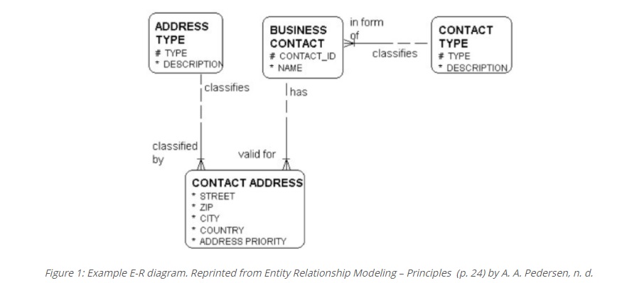
Utilize a graphics tool or Database Modeler tool to create an E-R diagram. A free tool that can be used is DIA, which is available at http://dia-installer.de/download/index.html.en. You can also use any tool that can produce a standard E-R diagram. Your tool must be capable of displaying the standard format of entities and relationships as illustrated in the Pedersen, A. A. (n. d.) in Figure 1.
Figure 1.

Some valid tools include DBModeler, Microsoft Visio, PowerPoint, OpenOffice Draw, OpenOffice Impress. Whichever tool you use you must be able to copy your results into a Word document for your final submission.
If you use either OpenOffice Draw or Impress you will need to get arrows for your connecting lines that have the standard crows foot notation used in E-R diagrams.
In the hospital, there is a reporting relationship between the head doctor and other doctors that report to the head doctor. This is known as a Unary relationship. You must be able to both describe and model this relationship within your relation and within your Entity Relationship diagram.
Your assignment must include the following:
- An Entity Relationship (E-R) diagram that defines the following relations and the relationships between them:
- Doctor
- Patient
- Appointment
- Each entity must include appropriate attributes and primary keys
- Each relationship must be labeled with the cardinality of the relationship
- The unary relationship must be described
Be sure to copy images and paste them directly into your document. It would be recommended that you document your relations in the manner used in the example assignment provided in this unit.
References
Pedersen, A. A. (n. d.). Entity Relationship Modeling Principles.
in form ADDRESS TYPE # TYPE * DESCRIPTION classifies classifies BUSINESS CONTACT # CONTACT_ID NAME Thas | CONTACT TYPE # TYPE DESCRIPTION classified by valid for CONTACT ADDRESS * STREET ZIP CITY COUNTRY ADDRESS PRIORITY Figure 1: Example E-R diagram. Reprinted from Entity Relationship Modeling - Principles (p. 24) by A. A. Pedersen, n. d
Step by Step Solution
There are 3 Steps involved in it

Get step-by-step solutions from verified subject matter experts


