

Answered step by step
Verified Expert Solution
Question
1 Approved Answer
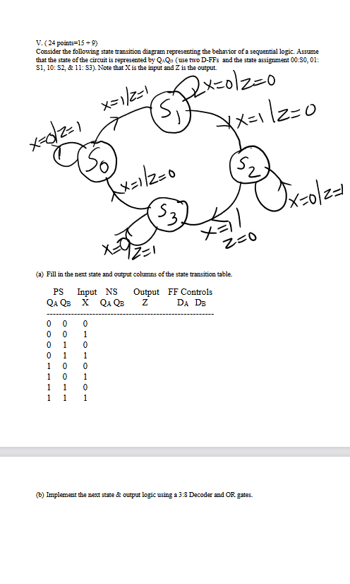
V. (24 points=15+9) Consider the following state transition diagram representing the behavior of a sequential logic. Assume that the state of the circuit is represented
Step by Step Solution
There are 3 Steps involved in it
Step: 1

Get Instant Access to Expert-Tailored Solutions
See step-by-step solutions with expert insights and AI powered tools for academic success
Step: 2

Step: 3
Ace Your Homework with AI
Get the answers you need in no time with our AI-driven, step-by-step assistance
Get Started
SQL Server Database Programming With Visual Basic.NET Concepts Designs And Implementations
Authors: Ying Bai
1st Edition
1119608503, 978-1119608509