Answered step by step
Verified Expert Solution
Question
1 Approved Answer
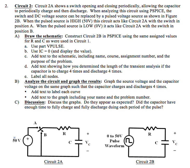
Values for R and C were, R=238 ohms and C=567 uF. IC =67 V. Please include all steps. Thank you. 2. Circuit 2: Circuit 2A

Values for R and C were, R=238 ohms and C=567 uF. IC =67 V.
Please include all steps. Thank you.
2. Circuit 2: Circuit 2A shows a switch opening and closing periodically, allowing the capacitor to periodically charge and then discharge. When analyzing this circuit using PSPICE, the switch and DC voltage source can be replaced by a pulsed voltage source as shown in Figure 2B. When the pulsed source is HIGH (50V) this circuit acts like Circuit 2A with the switch in position A. When the pulsed source is LOW (0V) it acts like Circuit 2A with the switch in position B A) Draw the schematic: Construct Circuit 2B in PSPICE using the same assigned values for R and C as were used in Circui a. Use part VPULSE b. Use IC 0 (and display the value) c. Add text to the schematic, including name, course, assignment number, and the purpose of the problem d. Add text showing how you determined the length of the transient analysis if the capacitor is to charge 4 times and discharge 4 times Label all nodes e. Analyze the circuit and graph the results: Graph the source voltage and the capacitor voltage on the same graph such that the capacitor charges and discharges 4 times B) Add text to label each curve * Add text to the graph including your name and the problem number Discussion: Discuss the graphs. Do they appear as expected? Did the capacitor have enough time to fully charge and fully discharge duing each period of the pulse? C) 0 to 50V Pulse Waveform 50V Circuit 2A Circuit 2B 2. Circuit 2: Circuit 2A shows a switch opening and closing periodically, allowing the capacitor to periodically charge and then discharge. When analyzing this circuit using PSPICE, the switch and DC voltage source can be replaced by a pulsed voltage source as shown in Figure 2B. When the pulsed source is HIGH (50V) this circuit acts like Circuit 2A with the switch in position A. When the pulsed source is LOW (0V) it acts like Circuit 2A with the switch in position B A) Draw the schematic: Construct Circuit 2B in PSPICE using the same assigned values for R and C as were used in Circui a. Use part VPULSE b. Use IC 0 (and display the value) c. Add text to the schematic, including name, course, assignment number, and the purpose of the problem d. Add text showing how you determined the length of the transient analysis if the capacitor is to charge 4 times and discharge 4 times Label all nodes e. Analyze the circuit and graph the results: Graph the source voltage and the capacitor voltage on the same graph such that the capacitor charges and discharges 4 times B) Add text to label each curve * Add text to the graph including your name and the problem number Discussion: Discuss the graphs. Do they appear as expected? Did the capacitor have enough time to fully charge and fully discharge duing each period of the pulse? C) 0 to 50V Pulse Waveform 50V Circuit 2A Circuit 2BStep by Step Solution
There are 3 Steps involved in it
Step: 1

Get Instant Access to Expert-Tailored Solutions
See step-by-step solutions with expert insights and AI powered tools for academic success
Step: 2

Step: 3

Ace Your Homework with AI
Get the answers you need in no time with our AI-driven, step-by-step assistance
Get Started


