Question
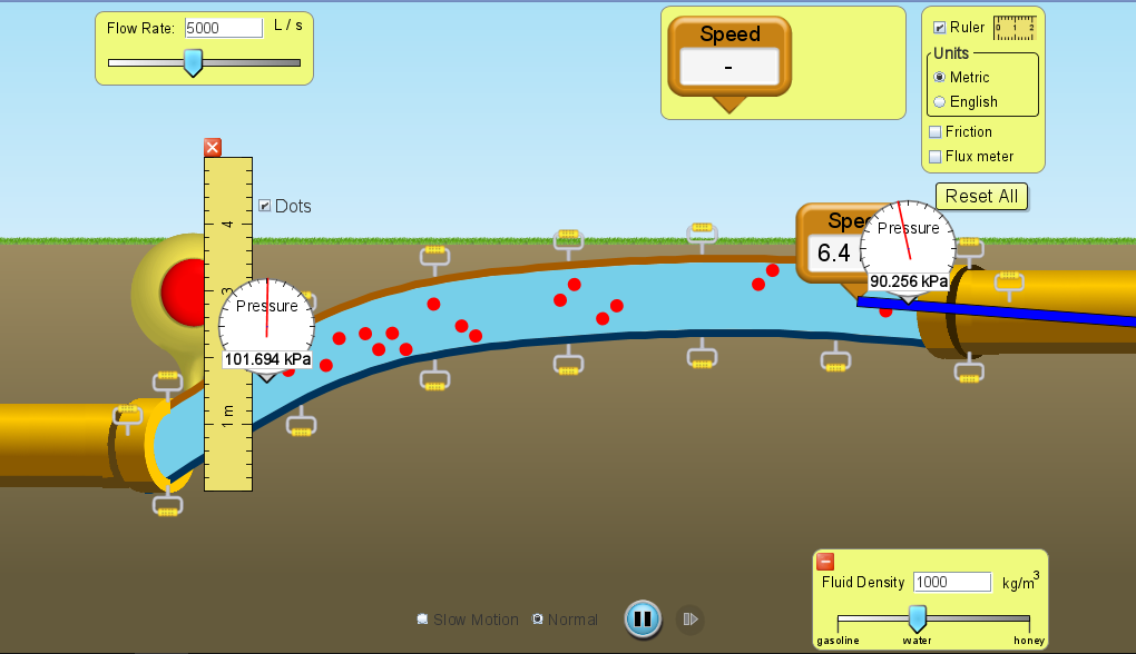
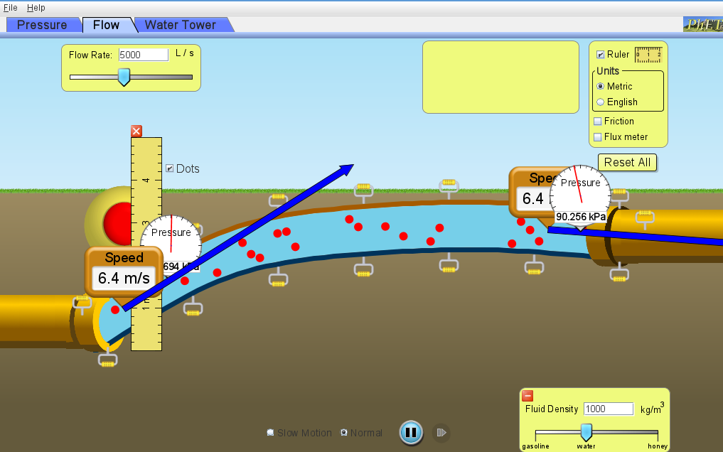
Water was chosen as the fluid. It was changed to position of the conduits according to the figure and the control volume was defined (point
Water was chosen as the fluid. It was changed to position of the conduits according to the figure and the control volume was defined (point 1 - beginning of the pipeline and 2 - end of the pipeline) to obtain the velocity at point 1.
The pressure and velocity gauges were positioned in the center of the pipeline at point 2 and the pressure gauge at point 1.
Find the velocity at point 1 mathematically by applying Bernoulli's equation and doing the analyzes coherently of the variables that can be neglected.

After the calculations with the speed meter in the center of the pipe at point 1 and compare the results of the simulator with the results found mathematically with the application of Bernoulli equation.


Data: Pressure at point 1: 101,694kPa Pressure at point 2: 90.256kPa Speed at point 2: 6.4m/s What is asked is to calculate the velocity at point 1 and compare it with the simulator value of 6.4 m/s at point 1
z1+2gv12+p1=z2+2gv22+p2 File Help Pressure Flow Water Tower Ruler Units Metric English Friction Flux meter Reset All Speed - Pressure 6.4m/s 694Step by Step Solution
There are 3 Steps involved in it
Step: 1

Get Instant Access to Expert-Tailored Solutions
See step-by-step solutions with expert insights and AI powered tools for academic success
Step: 2

Step: 3

Ace Your Homework with AI
Get the answers you need in no time with our AI-driven, step-by-step assistance
Get Started


