Answered step by step
Verified Expert Solution
Question
1 Approved Answer
Using verilog create a component with the following connections: module alu(clk, control, A, B, result); clk is an input clock signal (1 bit) control
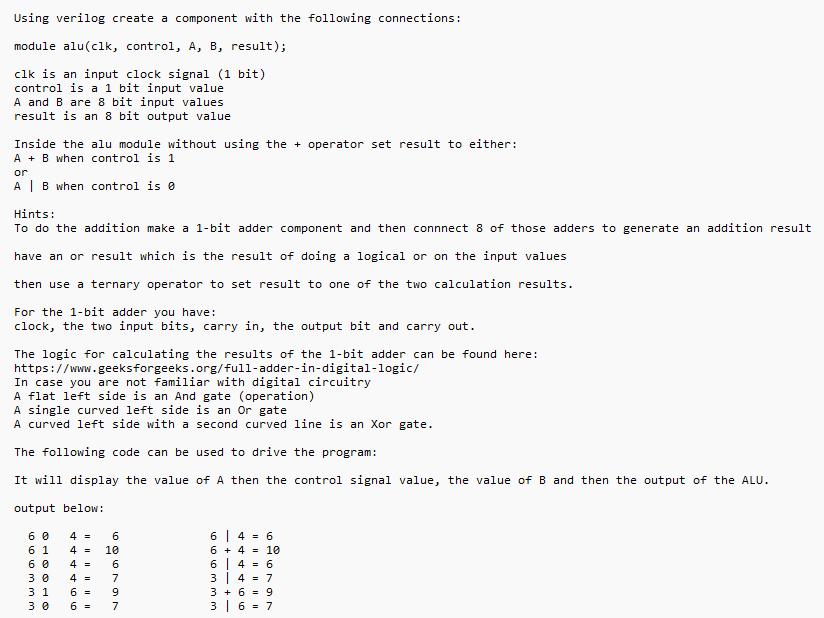
Using verilog create a component with the following connections: module alu(clk, control, A, B, result); clk is an input clock signal (1 bit) control is a 1 bit input value A and B are 8 bit input values result is an 8 bit output value Inside the alu module without using the + operator set result to either: AB when control is 1. or A | B when control is 0 Hints: To do the addition make a 1-bit adder component and then connnect 8 of those adders to generate an addition result have an or result which is the result of doing a logical or on the input values then use a ternary operator to set result to one of the two calculation results. For the 1-bit adder you have: clock, the two input bits, carry in, the output bit and carry out. The logic for calculating the results of the 1-bit adder can be found here: https://www.geeks forgeeks.org/full-adder-in-digital-logic/ In case you are not familiar with digital circuitry A flat left side is an And gate (operation) A single curved left side is an Or gate A curved left side with a second curved line is an Xor gate. The following code can be used to drive the program: It will display the value of A then the control signal value, the value of B and then the output of the ALU. output below: 60 4 = 6 61 4 = 10 646 6410 6 0 4 = 6 646 30 4 = 7 347 31 6 = 9 3+69 30 6 = 7 36 7
Step by Step Solution
There are 3 Steps involved in it
Step: 1

Get Instant Access to Expert-Tailored Solutions
See step-by-step solutions with expert insights and AI powered tools for academic success
Step: 2

Step: 3

Ace Your Homework with AI
Get the answers you need in no time with our AI-driven, step-by-step assistance
Get Started


