

Answered step by step
Verified Expert Solution
Question
1 Approved Answer
What error is present in Figure 2.6 of the textbook? 2.7 Symbols Used For Logic Gates When they design circuits, engineers think about interconnecting logic
What error is present in Figure 2.6 of the textbook?
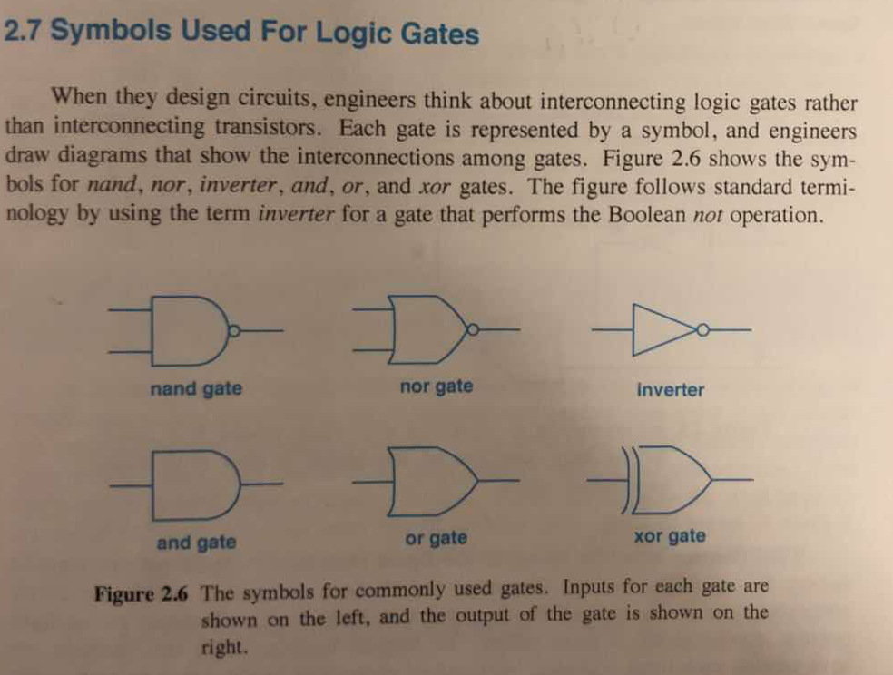
2.7 Symbols Used For Logic Gates When they design circuits, engineers think about interconnecting logic gates rather than interconnecting transistors. Each gate is represented by a symbol, and engineers draw diagrams that show the interconnections among gates. Figure 2.6 shows the sym- bols for nand, nor, inverter, and, or, and xor gates. The figure follows standard termi- nology by using the term inverter for a gate that performs the Boolean not operation. nand gate nor gate inverter and gate or gate xor gate Figure 2.6 The symbols for commonly used gates. Inputs for each gate are shown on the left, and the output of the gate is shown on the rightStep by Step Solution
There are 3 Steps involved in it
Step: 1

Get Instant Access to Expert-Tailored Solutions
See step-by-step solutions with expert insights and AI powered tools for academic success
Step: 2

Step: 3
Ace Your Homework with AI
Get the answers you need in no time with our AI-driven, step-by-step assistance
Get Started
Advances In Databases And Information Systems 14th East European Conference Adbis 2010 Novi Sad Serbia September 2010 Proceedings Lncs 6295
Authors: Barbara Catania ,Mirjana Ivanovic ,Bernhard Thalheim
2010th Edition
3642155758, 978-3642155758