

Answered step by step
Verified Expert Solution
Question
1 Approved Answer
WHEATSTONE BRIDGE DATA SHEET igital Multi-meter readings and theoretical values Introduction The Wheatstone bridge is an electrical circuit used to compare an unknown resistance with
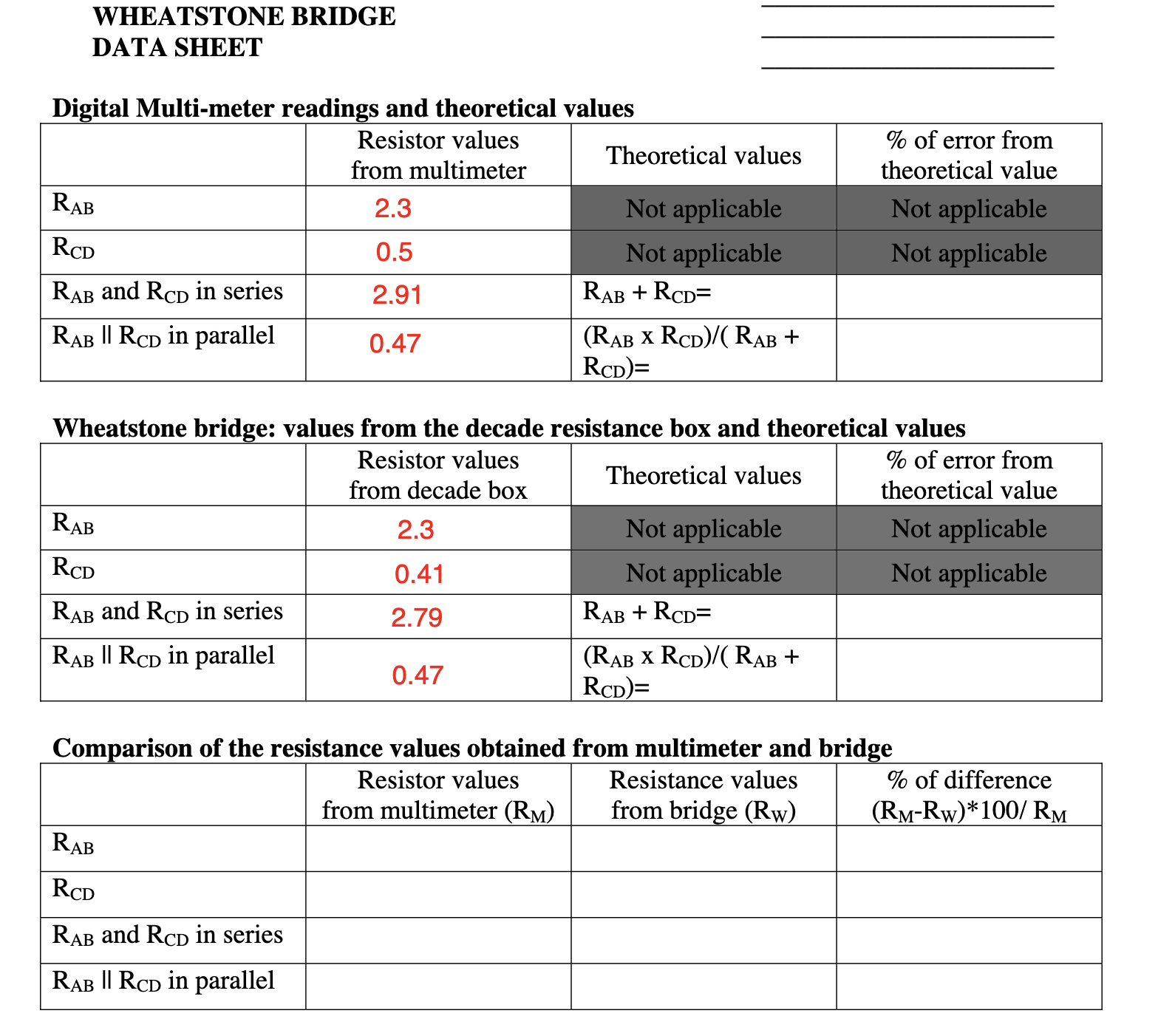
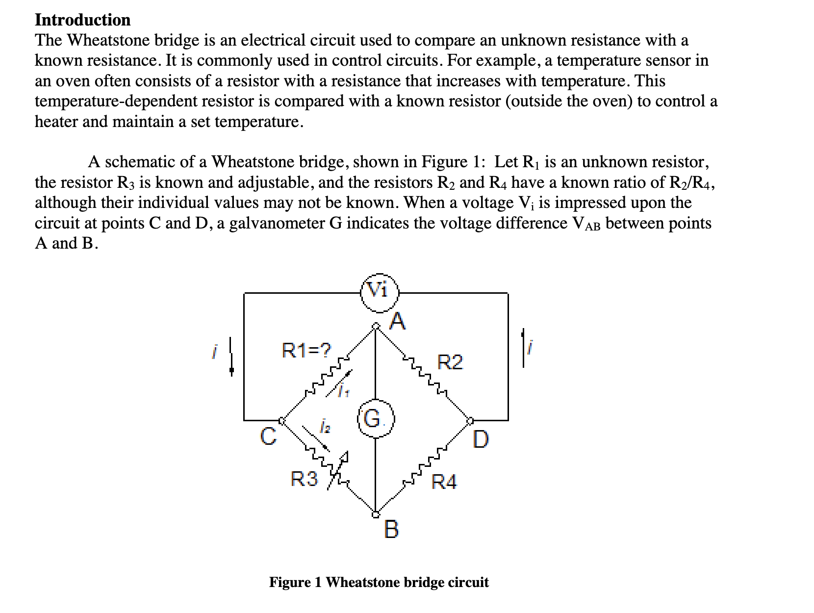
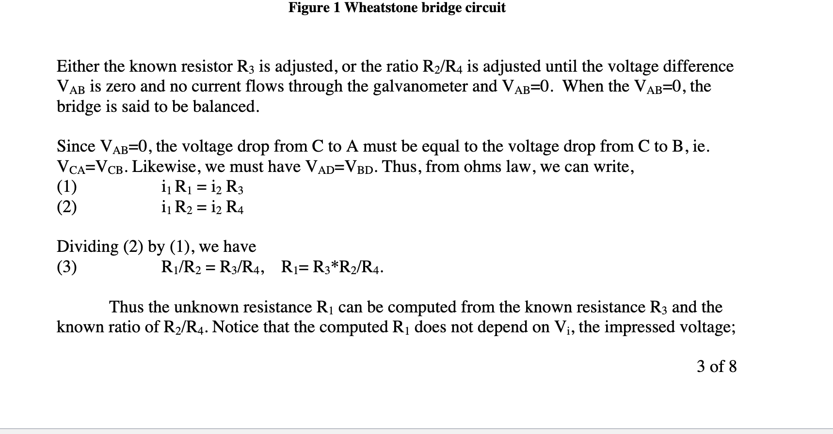
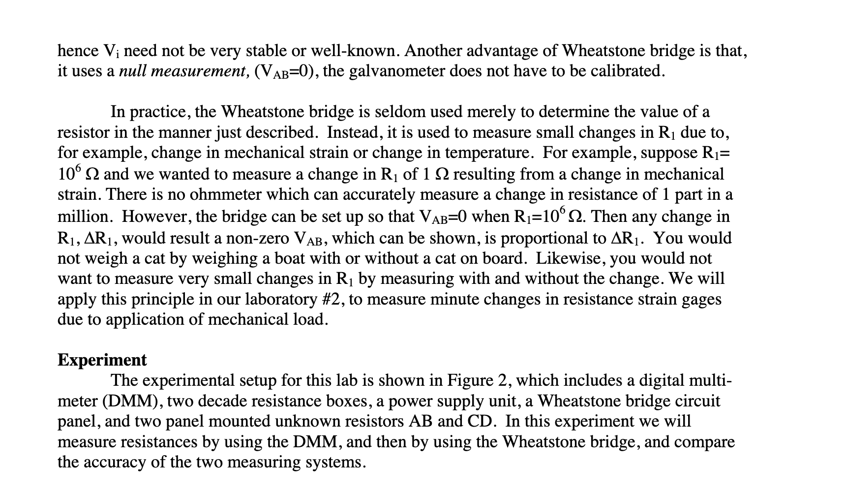
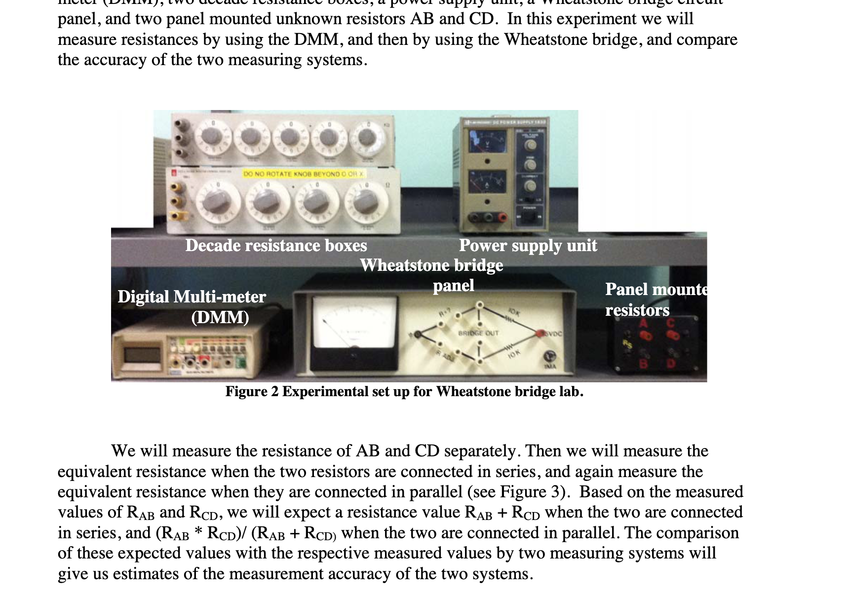
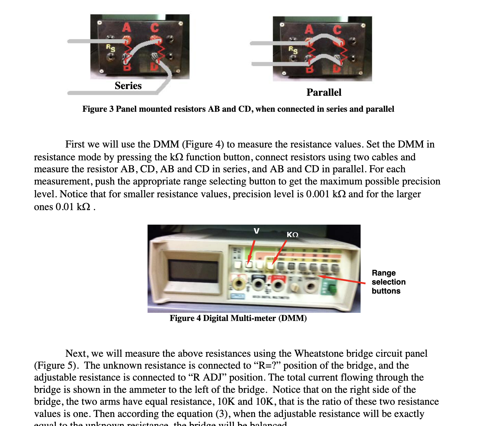
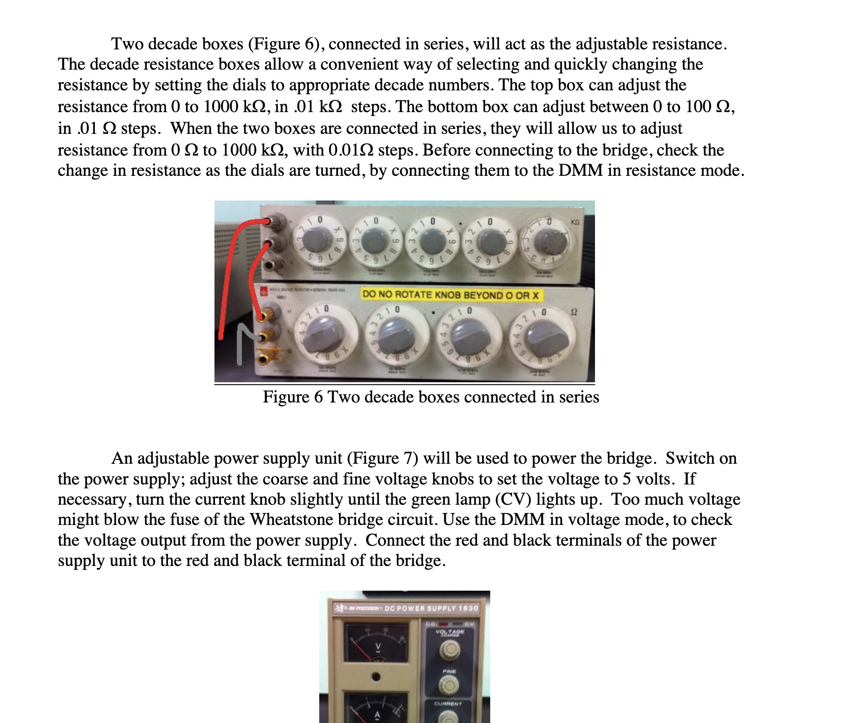
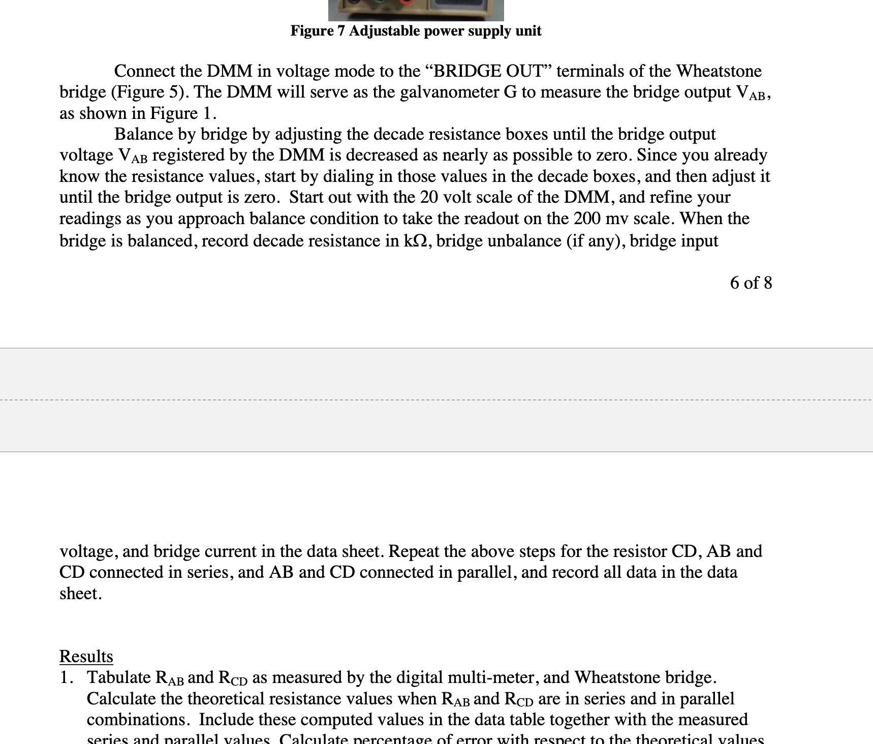 WHEATSTONE BRIDGE DATA SHEET igital Multi-meter readings and theoretical values Introduction The Wheatstone bridge is an electrical circuit used to compare an unknown resistance with a known resistance. It is commonly used in control circuits. For example, a temperature sensor in an oven often consists of a resistor with a resistance that increases with temperature. This temperature-dependent resistor is compared with a known resistor (outside the oven) to control a heater and maintain a set temperature. A schematic of a Wheatstone bridge, shown in Figure 1: Let R1 is an unknown resistor, the resistor R3 is known and adjustable, and the resistors R2 and R4 have a known ratio of R2/R4, although their individual values may not be known. When a voltage Vi is impressed upon the circuit at points C and D, a galvanometer G indicates the voltage difference VAB between points A and B. Figure 1 Wheatstone bridge circuit Figure 1 Wheatstone bridge circuit Either the known resistor R3 is adjusted, or the ratio R2/R4 is adjusted until the voltage difference VAB is zero and no current flows through the galvanometer and VAB=0. When the VAB=0, the bridge is said to be balanced. Since VAB=0, the voltage drop from C to A must be equal to the voltage drop from C to B, ie. VCA=VCB. Likewise, we must have VAD=VBD. Thus, from ohms law, we can write, i1R1=i2R3i1R2=i2R4 Dividing (2) by (1), we have R1/R2=R3/R4,R1=R3R2/R4. Thus the unknown resistance R1 can be computed from the known resistance R3 and the known ratio of R2/R4. Notice that the computed R1 does not depend on Vi, the impressed voltage; 3 of 8 hence Vi need not be very stable or well-known. Another advantage of Wheatstone bridge is that, it uses a null measurement, (VAB=0), the galvanometer does not have to be calibrated. In practice, the Wheatstone bridge is seldom used merely to determine the value of a resistor in the manner just described. Instead, it is used to measure small changes in R1 due to, for example, change in mechanical strain or change in temperature. For example, suppose R1= 106 and we wanted to measure a change in R1 of 1 resulting from a change in mechanical strain. There is no ohmmeter which can accurately measure a change in resistance of 1 part in a million. However, the bridge can be set up so that VAB=0 when R1=106. Then any change in R1,R1, would result a non-zero VAB, which can be shown, is proportional to R1. You would not weigh a cat by weighing a boat with or without a cat on board. Likewise, you would not want to measure very small changes in R1 by measuring with and without the change. We will apply this principle in our laboratory \#2, to measure minute changes in resistance strain gages due to application of mechanical load. Experiment The experimental setup for this lab is shown in Figure 2, which includes a digital multimeter (DMM), two decade resistance boxes, a power supply unit, a Wheatstone bridge circuit panel, and two panel mounted unknown resistors AB and CD. In this experiment we will measure resistances by using the DMM, and then by using the Wheatstone bridge, and compare the accuracy of the two measuring systems. panel, and two panel mounted unknown resistors AB and CD. In this experiment we will measure resistances by using the DMM, and then by using the Wheatstone bridge, and compare the accuracy of the two measuring systems. Figure 2 Experimental set up for Wheatstone bridge lab. We will measure the resistance of AB and CD separately. Then we will measure the equivalent resistance when the two resistors are connected in series, and again measure the equivalent resistance when they are connected in parallel (see Figure 3). Based on the measurec values of RAB and RCD, we will expect a resistance value RAB+RCD when the two are connectec in series, and (RABRCD)/(RAB+RCD ) when the two are connected in parallel. The comparison of these expected values with the respective measured values by two measuring systems will give us estimates of the measurement accuracy of the two systems. Parallel Figure 3 Panel mounted resistors AB and CD, when connected in series and parallel First we will use the DMM (Figure 4) to measure the resistance values. Set the DMM in resistance mode by pressing the k function button, connect resistors using two cables and measure the resistor AB,CD,AB and CD in series, and AB and CD in parallel. For each measurement, push the appropriate range selecting button to get the maximum possible precision level. Notice that for smaller resistance values, precision level is 0.001k and for the larger ones 0.01k. Next, we will measure the above resistances using the Wheatstone bridge circuit panel (Figure 5). The unknown resistance is connected to " R= ?" position of the bridge, and the adjustable resistance is connected to "R ADJ" position. The total current flowing through the bridge is shown in the ammeter to the left of the bridge. Notice that on the right side of the bridge, the two arms have equal resistance, 10K and 10K, that is the ratio of these two resistance values is one. Then according the equation (3), when the adjustable resistance will be exactly Two decade boxes (Figure 6), connected in series, will act as the adjustable resistance. The decade resistance boxes allow a convenient way of selecting and quickly changing the resistance by setting the dials to appropriate decade numbers. The top box can adjust the resistance from 0 to 1000k, in .01k steps. The bottom box can adjust between 0 to 100, in .01 steps. When the two boxes are connected in series, they will allow us to adjust resistance from 0 to 1000k, with 0.01 steps. Before connecting to the bridge, check the change in resistance as the dials are turned, by connecting them to the DMM in resistance mode. Figure 6 Two decade boxes connected in series An adjustable power supply unit (Figure 7) will be used to power the bridge. Switch on the power supply; adjust the coarse and fine voltage knobs to set the voltage to 5 volts. If necessary, turn the current knob slightly until the green lamp (CV) lights up. Too much voltage might blow the fuse of the Wheatstone bridge circuit. Use the DMM in voltage mode, to check the voltage output from the power supply. Connect the red and black terminals of the power supply unit to the red and black terminal of the bridge. Figure 7 Adjustable power supply unit Connect the DMM in voltage mode to the "BRIDGE OUT" terminals of the Wheatstone bridge (Figure 5). The DMM will serve as the galvanometer G to measure the bridge output VAB, as shown in Figure 1. Balance by bridge by adjusting the decade resistance boxes until the bridge output voltage VAB registered by the DMM is decreased as nearly as possible to zero. Since you already know the resistance values, start by dialing in those values in the decade boxes, and then adjust it until the bridge output is zero. Start out with the 20 volt scale of the DMM, and refine your readings as you approach balance condition to take the readout on the 200mv scale. When the bridge is balanced, record decade resistance in k, bridge unbalance (if any), bridge input 6 of 8 voltage, and bridge current in the data sheet. Repeat the above steps for the resistor CD,AB and CD connected in series, and AB and CD connected in parallel, and record all data in the data sheet. Results 1. Tabulate RAB and RCD as measured by the digital multi-meter, and Wheatstone bridge. Calculate the theoretical resistance values when RAB and RCD are in series and in parallel combinations. Include these computed values in the data table together with the measured
Step by Step Solution
There are 3 Steps involved in it
Step: 1

Get Instant Access to Expert-Tailored Solutions
See step-by-step solutions with expert insights and AI powered tools for academic success
Step: 2

Step: 3
Ace Your Homework with AI
Get the answers you need in no time with our AI-driven, step-by-step assistance
Get Started
Fundamentals Of Hydraulic Engineering Systems
Authors: Robert J. Houghtalen, A. Osman H. Akan, Ned H. C. Hwang
4th Edition