Question: Wireless LAN Components Wireless LANs operate a multitude of devices, such as PCs, laptops and PDAs. A major part of a wireless LAN includes


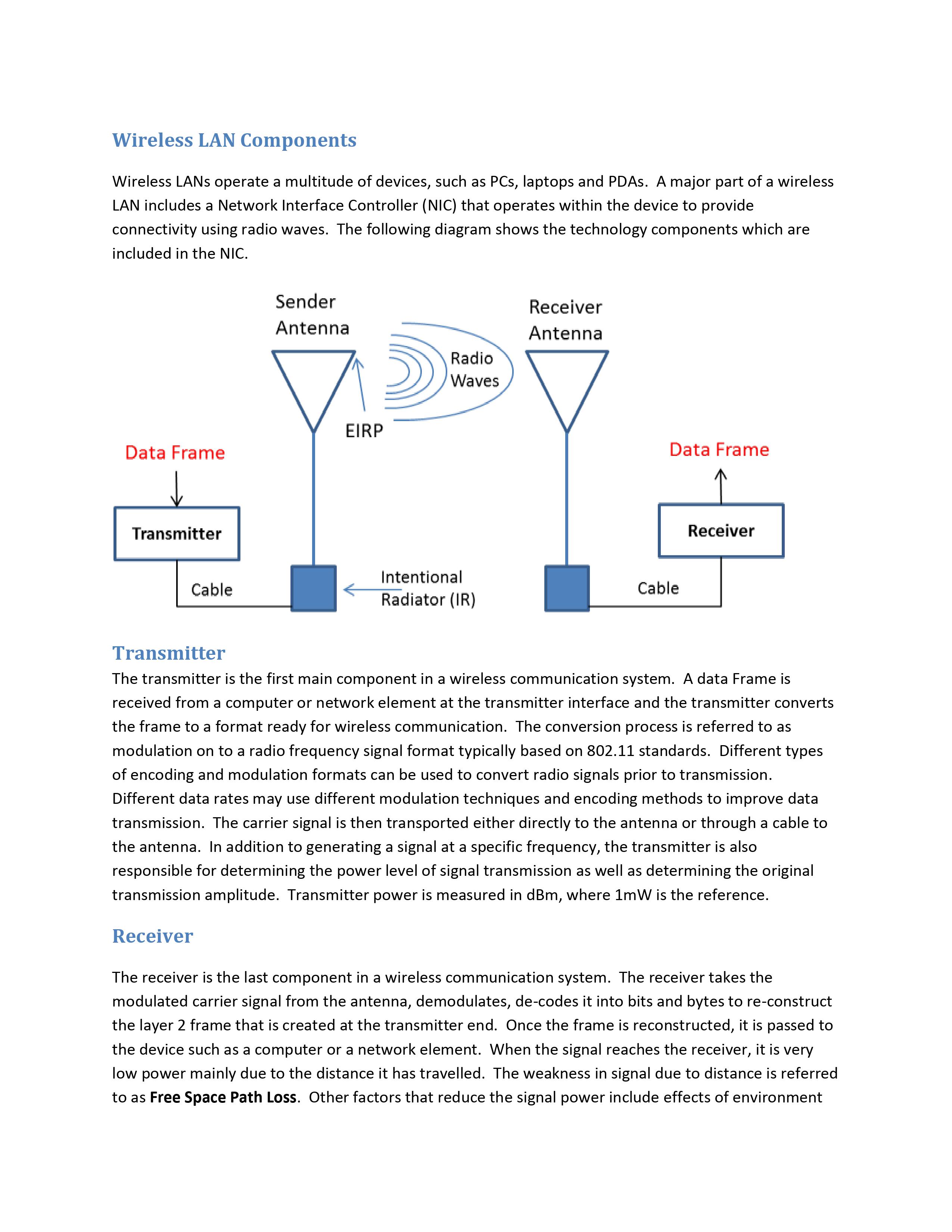
Wireless LAN Components Wireless LANs operate a multitude of devices, such as PCs, laptops and PDAs. A major part of a wireless LAN includes a Network Interface Controller (NIC) that operates within the device to provide connectivity using radio waves. The following diagram shows the technology components which are included in the NIC. Data Frame Transmitter Cable Sender Antenna EIRP Radio Waves Intentional Radiator (IR) Receiver Antenna Data Frame Cable Receiver Transmitter The transmitter is the first main component in a wireless communication system. A data Frame is received from a computer or network element at the transmitter interface and the transmitter converts the frame to a format ready for wireless communication. The conversion process is referred to as modulation on to a radio frequency signal format typically based on 802.11 standards. Different types of encoding and modulation formats can be used to convert radio signals prior to transmission. Different data rates may use different modulation techniques and encoding methods to improve data transmission. The carrier signal is then transported either directly to the antenna or through a cable to the antenna. In addition to generating a signal at a specific frequency, the transmitter is also responsible for determining the power level of signal transmission as well as determining the original transmission amplitude. Transmitter power is measured in dBm, where 1mW is the reference. Receiver The receiver is the last component in a wireless communication system. The receiver takes the modulated carrier signal from the antenna, demodulates, de-codes it into bits and bytes to re-construct the layer 2 frame that is created at the transmitter end. Once the frame is reconstructed, it is passed to the device such as a computer or a network element. When the signal reaches the receiver, it is very low power mainly due to the distance it has travelled. The weakness in signal due to distance is referred to as Free Space Path Loss. Other factors that reduce the signal power include effects of environment such as geographical location, structures, walls, humidity, terrain, interference from other RF sources, reflection loss and Fresnel loss. Received power is measured in dBm, where 1mW is the reference. Intentional Radiator The standards body defines Intentional Radiator (IR) as the device that generates frequency intentionally to be used as application utilizing generated frequency. The frequency generated is emitted either using induction or radiation. The component is called intentional because its purpose is to generate frequency, unlike an electric motor that radiates frequency as a by-product that causes noise often picked up by antennas in its vicinity. The power output of the IR is the sum of all the components between transmitter and antenna excluding the transmitter and antenna. The power of the IR is measured at the connector that provides input to the antenna and is usually measured in dBm, relative to 1 mW. Cables and Connectors Cables and connectors are used in wireless communications to connect all components together. The wireless technology components may be installed at a distance from each other. The cables and connectors reduce the power from the transmitter and to the receiver. The power loss caused by cables and connectors is measured in dBm, relative to 1 mW. Antenna An antenna is used at both the transmitter end and at the receiver end. When connected to the transmitter, it collects AC signals that it receives from the transmitter and directs or radiates the Radio Frequency (RF) waves away from the antenna in a pattern specific to the antenna type. The signal from the transmitter is already encoded with data and modulated for transmission. When connected to the receiver, the antenna takes the RF waves that it receives through the air and directs the AC signal to the receiver. The receiver converts the AC signal to bits and bytes. Transmitting antenna is usually termed as "isotropic radiator", if it is simple omni-directional antenna. An isotropic antenna radiates the signal equally in all directions in a round globe like pattern. Radiated Power can be enhanced by increasing the signal power level or increasing the directionality of the radiated signal. In mathematical calculations and theoretical models, we define an Ideal antenna as a hypothetical isotropic radiator. Increasing the radiated signal directionality is called antenna Gain. Gain is calculated by measuring the antenna power in a specific direction and comparing the value to the power of an ideal antenna, both having identical transmitter parameters. Antenna gain is measured in dBi, where the reference is an isotropic radiator. Equivalent Isotropically Radiated Power The maximum signal strength that is transmitted from an antenna in a specific direction is referred to as Equivalent Isotropically Radiated Power (EIRP). An isotropical antenna radiates energy equally in all directions but it can direct energy in a specific direction (antenna gain). The ability of an antenna to direct power in a specific direction is equivalent to increasing the power in that direction. The EIRP is calculated by multiplying the transmitter power by the antenna gain. Since antenna power and transmitter power are both measured in dB, EIRP can be calculated by adding transmitter power to antenna gain and subtracting cable loss. General formula is: EIRP = Output Power(dBm) + Antenna Gain(dBi) Cable Loss(dBm) Questions 1. List 4 components of a wireless NIC: 2. What is an IR? 3. What is an EIRP? 4. What common 802 standard defines wireless LAN operation? 5. Which component is responsible for determining the power level of a signal? 6. What is Free Space Path Loss? 7. Explain the difference between dBm and dBi. 8. What is the main purpose of an IR? 9. Name two types of antenna. 10. What energy form are the input and output of an antenna? 11. What is an isotropic radiator? 12. Define antenna Gain. 13. What is the effect of cables and connectors on signal power? 14. If the power of a transmitter is -30dBm and the antenna gain is -10dBi, calculate EIRP assuming that the cable loss is -5dBm. 15. A wireless signal has power of -65dBm at the receiver antenna. The antenna gain is -10dBi and is connected with 2 cables to the receiver. Each cable accounts for -3dBm loss. Calculate the power at the receiver.
Step by Step Solution
There are 3 Steps involved in it

Get step-by-step solutions from verified subject matter experts


