Work this with VHDL, Design an Interrupt Controller. It will consist of the data path model made up of registers, busses, priority encoder, interrupt FFs, combinational logic, and interconnection tri-state buffers.
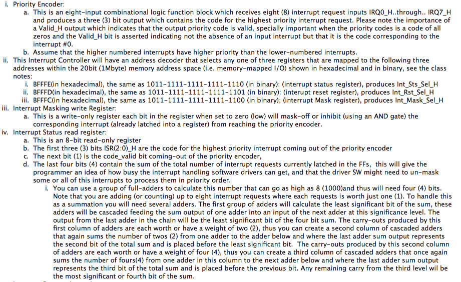
Priority Encoder: a. This is an eight-input combinational logic function block which receives eight (8) interrupt request inputs IRQ0 H..through.. IRQ7 H and produces a three (3) bit output which contains the code for the highest priority interrupt request. Please note the importance of a Valid H output which indicates that the output priority code is valid, specially important when the priority codes is a code of all zeros and the Valid H bit is asserted indicating not the absence of an input interrupt but that it is the code corresponding to the interrupt #0 b. Assume that the higher numbered interrupts have higher priority than the lower-numbered interrupts This Interrupt Controller will have an address decoder that selects any one o f three registers that are mapp ed to the following three addresses within the 20bit te) memory address space e. memory-mapped I/O) shown in hexadecimal and in binary, see the class notes n hexadecimal), the same as 1011-1111-1111-1111-1110 (in binary): (interrupt status register), produces Int Sts Sel H BFFFD(in hexadecimal), the same as 1011-1111-1111-1111-1101 (in binary): (interupt reset register, produces In Rst Sel H BFFFC(in hexadecimal), the same as 1011-1111-1111-1111-1100 (in binary); interrupt Mask register), produces Int Mask Sel H iii. Interrupt Masking write Register w a. This is a write-only register each bit in the register when set to zero (low) I mask-off or inhibit (using an AND gate) the corresponding interrupt (already latched into a register) from reaching the priority encoder Interrupt Status read register a. This is an 8-bit read-only register b. The first three (3) bits ISR(2:0) H are the code for the highest priority interrupt coming out of the prio encoder The next bit (1) is the code valid bit coming-out of the priority encoder, d. The last four bits (4) contain the sum of the total number of interrupt requests currently latched in the FFs, this will give the programmer an idea of how busy the interrupt hand ng software drivers can get, and that the driver SW might need to un-mask some or all of this interrupts to process them in priority order You can use a group of fu adders to calculate this number that can go as high as 8 (1000)and thus wi need four (4) bits Note that you are adding (or counting) up to eight interrupt requests where each requests is worth just one (1). To handle this need several adders. The first group of adders wi calculate the least significant bit of the sum, these as a summation you wi adders will be cascaded feeding the sum output of one adder into an input of the next adder at this significance leve The output from the last adder in the chain will be the least significant bit of the four bit sum. The carry-outs produced by this first column of adders are each worth or have a weight of two (2), thus you can create a second column of cascaded adders that again sums the number of twos (2) rom one adder to the adder below and where the last adder sum output represents the second bit of the total sum and is placed before the least significant bit. The carry-outs produced by this second co umn of adders are each worth or have a weight of four (4), thus you can create a third column of cascaded adders that once again sums the number of fours(4) from one adder in this column to the next adder below and where the last adder sum output represents the third bit of the total sum and is placed before the previous bit. Any remaining carry from the third level wil be the most significant or fourth bit of the sum Priority Encoder: a. This is an eight-input combinational logic function block which receives eight (8) interrupt request inputs IRQ0 H..through.. IRQ7 H and produces a three (3) bit output which contains the code for the highest priority interrupt request. Please note the importance of a Valid H output which indicates that the output priority code is valid, specially important when the priority codes is a code of all zeros and the Valid H bit is asserted indicating not the absence of an input interrupt but that it is the code corresponding to the interrupt #0 b. Assume that the higher numbered interrupts have higher priority than the lower-numbered interrupts This Interrupt Controller will have an address decoder that selects any one o f three registers that are mapp ed to the following three addresses within the 20bit te) memory address space e. memory-mapped I/O) shown in hexadecimal and in binary, see the class notes n hexadecimal), the same as 1011-1111-1111-1111-1110 (in binary): (interrupt status register), produces Int Sts Sel H BFFFD(in hexadecimal), the same as 1011-1111-1111-1111-1101 (in binary): (interupt reset register, produces In Rst Sel H BFFFC(in hexadecimal), the same as 1011-1111-1111-1111-1100 (in binary); interrupt Mask register), produces Int Mask Sel H iii. Interrupt Masking write Register w a. This is a write-only register each bit in the register when set to zero (low) I mask-off or inhibit (using an AND gate) the corresponding interrupt (already latched into a register) from reaching the priority encoder Interrupt Status read register a. This is an 8-bit read-only register b. The first three (3) bits ISR(2:0) H are the code for the highest priority interrupt coming out of the prio encoder The next bit (1) is the code valid bit coming-out of the priority encoder, d. The last four bits (4) contain the sum of the total number of interrupt requests currently latched in the FFs, this will give the programmer an idea of how busy the interrupt hand ng software drivers can get, and that the driver SW might need to un-mask some or all of this interrupts to process them in priority order You can use a group of fu adders to calculate this number that can go as high as 8 (1000)and thus wi need four (4) bits Note that you are adding (or counting) up to eight interrupt requests where each requests is worth just one (1). To handle this need several adders. The first group of adders wi calculate the least significant bit of the sum, these as a summation you wi adders will be cascaded feeding the sum output of one adder into an input of the next adder at this significance leve The output from the last adder in the chain will be the least significant bit of the four bit sum. The carry-outs produced by this first column of adders are each worth or have a weight of two (2), thus you can create a second column of cascaded adders that again sums the number of twos (2) rom one adder to the adder below and where the last adder sum output represents the second bit of the total sum and is placed before the least significant bit. The carry-outs produced by this second co umn of adders are each worth or have a weight of four (4), thus you can create a third column of cascaded adders that once again sums the number of fours(4) from one adder in this column to the next adder below and where the last adder sum output represents the third bit of the total sum and is placed before the previous bit. Any remaining carry from the third level wil be the most significant or fourth bit of the sum