

Answered step by step
Verified Expert Solution
Question
1 Approved Answer
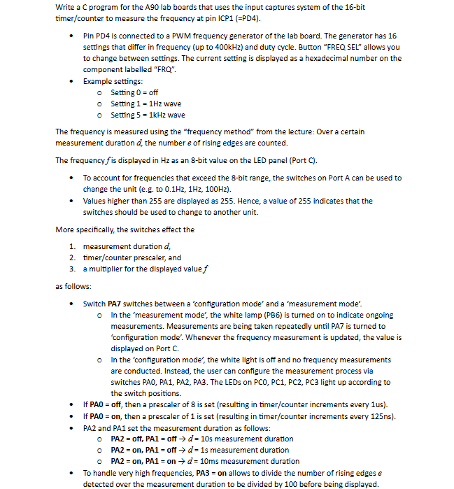
Write a C program for the A T 9 0 that uses the input captures system of the 1 6 - bit timer / counter
Write a C program for the that uses the input captures system of the bit
timercounter to measure the frequency at pin ICPPD
Pin PD is connected to a PWM frequency generator of the lab board. The generator has
settings that differ in frequency up to and duty cycle. Button "FREQ SEL" allows you
to change between settings. The current setting is displayed as a hexadecimal number on the
component labelled FRQ
Example settings:
Setting off
Setting wave
o Setting wave
The frequency is measured using the "frequency method" from the lecture: Over a certain
measurement duration the number of rising edges are counted.
The frequency is displayed in as an bit value on the LED panel Port C
To account for frequencies that exceed the bit range, the switches on Port A can be used to
change the unit eg to
Values higher than are displayed as Hence, a value of indicates that the
switches should be used to change to another unit.
More specifically, the switches effect the
measurement duration
timercounter prescaler, and
a multiplier for the displayed value
as follows:
Switch PA switches between a 'configuration mode' and a 'measurement mode'.
In the 'measurement mode', the white lamp PB is turned on to indicate ongoing
measurements. Measurements are being taken repeatedly until PA is turned to
'configuration mode'. Whenever the frequency measurement is updated, the value is
displayed on Port C
In the 'configuration mode', the white light is off and no frequency measurements
are conducted. Instead, the user can configure the measurement process via
switches PA PA PA PA The LEDs on PC PC PC PC light up according to
the switch positions.
If PA off, then a prescaler of is set resulting in timercounter increments every
If PA on then a prescaler of is set resulting in timercounter increments every
PA and PA set the measurement duration as follows:
PA off, PA off measurement duration
PA on PA off s measurement duration
PA on on ms measurement duration
To handle very high frequencies, on allows to divide the number of rising edges
detected over the measurement duration to be divided by before being displayed.
Step by Step Solution
There are 3 Steps involved in it
Step: 1

Get Instant Access to Expert-Tailored Solutions
See step-by-step solutions with expert insights and AI powered tools for academic success
Step: 2

Step: 3
Ace Your Homework with AI
Get the answers you need in no time with our AI-driven, step-by-step assistance
Get Started
Database And Expert Systems Applications 19th International Conference Dexa 2008 Turin Italy September 2008 Proceedings Lncs 5181
Authors: Sourav S. Bhowmick ,Josef Kung ,Roland Wagner
2008th Edition
3540856536, 978-3540856535