Answered step by step
Verified Expert Solution
Question
1 Approved Answer
Write a Verilog module for a 3-bit counter, called 'counter3b', and a testbench for the counter, called 'counter3b_tb'. The 'counter3b' module should output a 3-bit
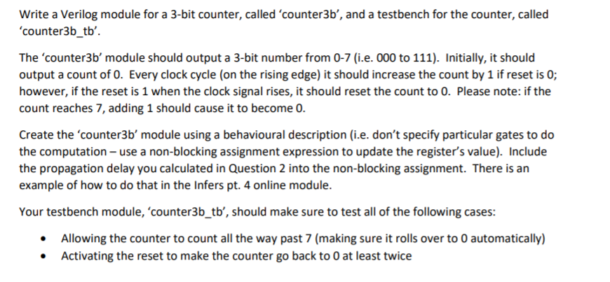
Write a Verilog module for a 3-bit counter, called 'counter3b', and a testbench for the counter, called 'counter3b_tb'. The 'counter3b' module should output a 3-bit number from 0-7 (i.e. 000 to 111). Initially, it should output a count of 0. Every clock cycle (on the rising edge) it should increase the count by 1 if reset is 0; however, if the reset is 1 when the clock signal rises, it should reset the count to 0. Please note: if the count reaches 7, adding 1 should cause it to become 0. Create the counter3b'module using a behavioural description (i.e. don't specify particular gates to do the computation - use a non-blocking assignment expression to update the register's value). Include the propagation delay you calculated in Question 2 into the non-blocking assignment. There is an example of how to do that in the Infers pt. 4 online module. Your testbench module, 'counter3b_tb', should make sure to test all of the following cases: Allowing the counter to count all the way past 7 (making sure it rolls over to 0 automatically) Activating the reset to make the counter go back to 0 at least twice
Step by Step Solution
There are 3 Steps involved in it
Step: 1
Get Instant Access to Expert-Tailored Solutions
See step-by-step solutions with expert insights and AI powered tools for academic success
Step: 2
Step: 3
Ace Your Homework with AI
Get the answers you need in no time with our AI-driven, step-by-step assistance
Get Started