Answered step by step
Verified Expert Solution
Question
1 Approved Answer
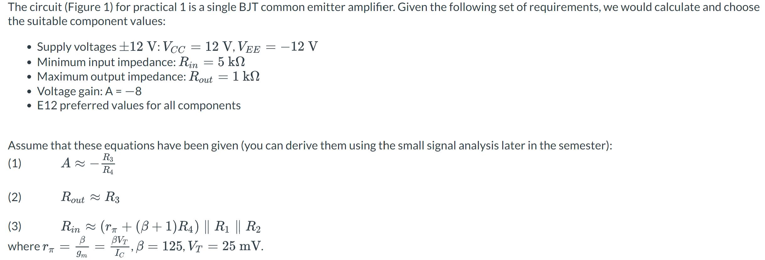
The circuit (Figure 1) for practical 1 is a single BJT common emitter amplifier. Given the following set of requirements, we would calculate and


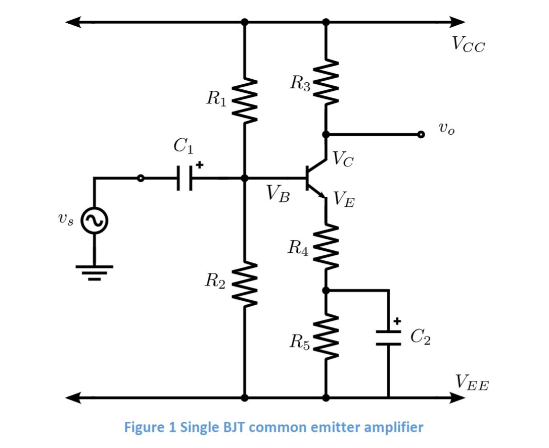
The circuit (Figure 1) for practical 1 is a single BJT common emitter amplifier. Given the following set of requirements, we would calculate and choose the suitable component values: Supply voltages +12 V: Vcc= 12 V, VEE = -12 V Minimum input impedance: Rin = 5 kn Maximum output impedance: Rout = 1 kN Voltage gain: A = -8 E12 preferred values for all components Assume that these equations have been given (you can derive them using the small signal analysis later in the semester): (1) A R3 R4 (2) (3) where r = Rout R3 Rin ~ ( + (B + 1)R4) || R1 || R B BVT B = 125, VT = 25 mV. Im Ic = Us C R R2 www ww R3 VB RA R5 Vc VE ww C Figure 1 Single BJT common emitter amplifier Vcc Vo VEE R5 is (E12 value) Type your answer... O points Step 4: Find R and R2 Consider replacing R and R with its Thevenin's equivalent circuit and then use Equation (3) to find the minimum value of Rth Assume VBE = 0.7 V. Hint: start by calculating VB and IB and then find the equations for Vth and Rth VB is_V = R || R.
Step by Step Solution
★★★★★
3.36 Rating (143 Votes )
There are 3 Steps involved in it
Step: 1
To find R5 we first need to determine the values of VE and IE emitter voltage and current The voltage at the emitter VE is found using the fact that the baseemitter junction of a BJT in the forwardact...
Get Instant Access to Expert-Tailored Solutions
See step-by-step solutions with expert insights and AI powered tools for academic success
Step: 2

Step: 3

Ace Your Homework with AI
Get the answers you need in no time with our AI-driven, step-by-step assistance
Get Started


