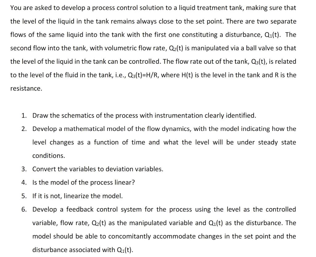
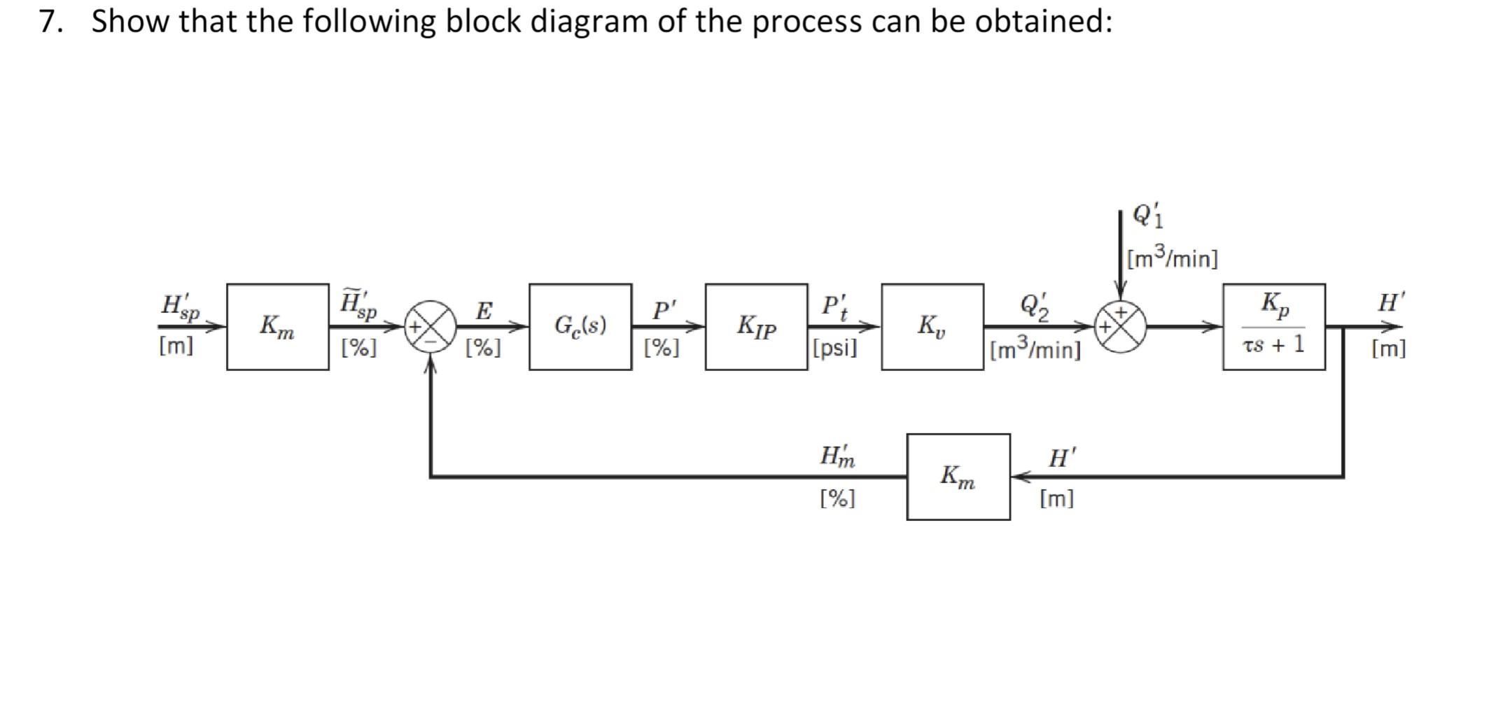
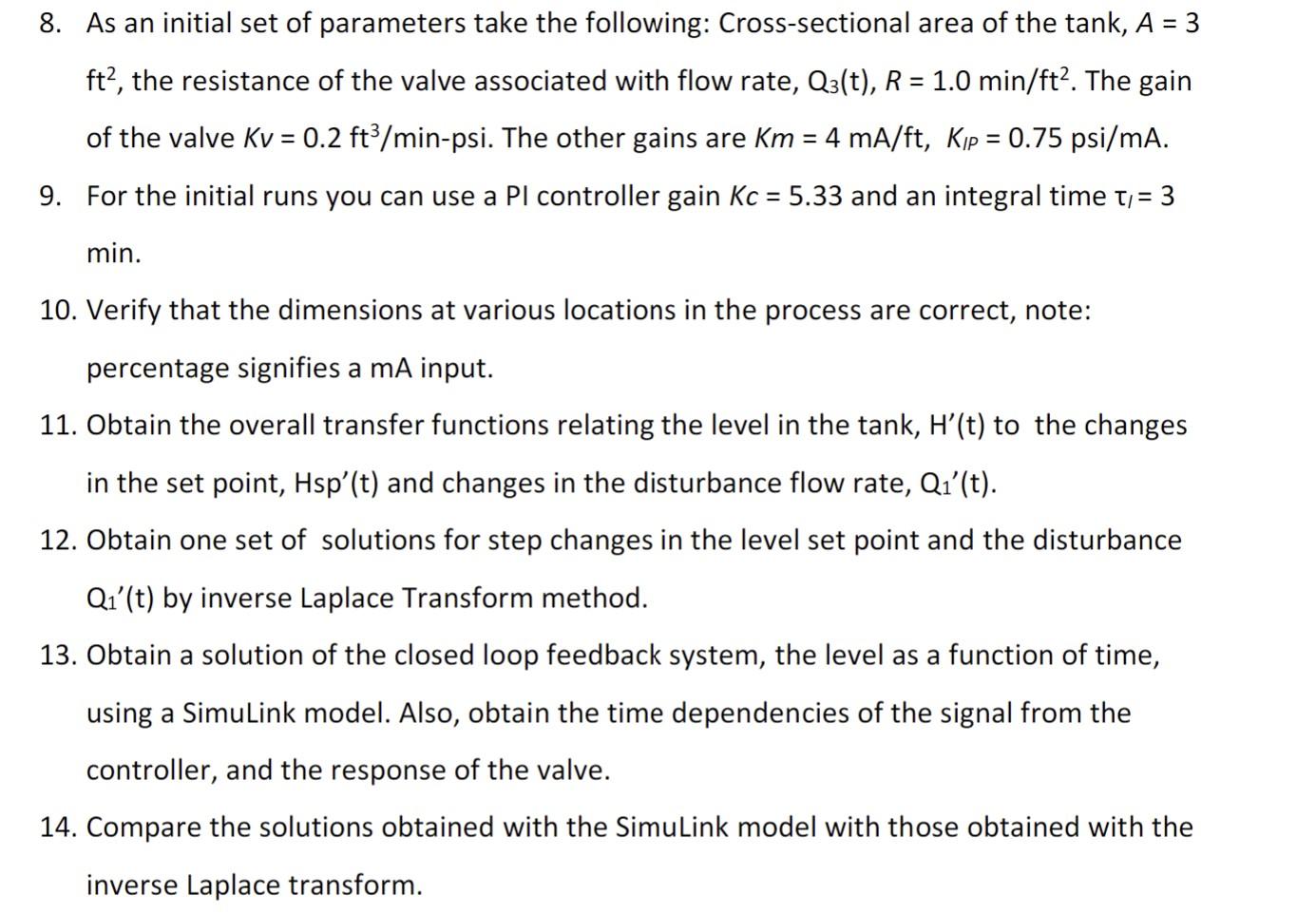
You are asked to develop a process control solution to a liquid treatment tank, making sure that the level of the liquid in the tank remains always close to the set point. There are two separate flows of the same liquid into the tank with the first one constituting a disturbance, Q1(t). The second flow into the tank, with volumetric flow rate, Q2(t) is manipulated via a ball valve so that the level of the liquid in the tank can be controlled. The flow rate out of the tank, Q3(t), is related to the level of the fluid in the tank, i.e., Q3(t)=H/R, where H(t) is the level in the tank and R is the resistance. 1. Draw the schematics of the process with instrumentation clearly identified. 2. Develop a mathematical model of the flow dynamics, with the model indicating how the level changes as a function of time and what the level will be under steady state conditions. 3. Convert the variables to deviation variables. 4. Is the model of the process linear? 5. If it is not, linearize the model. 6. Develop a feedback control system for the process using the level as the controlled variable, flow rate, Q2(t) as the manipulated variable and Q1(t) as the disturbance. The model should be able to concomitantly accommodate changes in the set point and the disturbance associated with Q1(t). 7. Show that the following block diagram of the process can be obtained: 8. As an initial set of parameters take the following: Cross-sectional area of the tank, A=3 ft2, the resistance of the valve associated with flow rate, Q3(t),R=1.0min/ft2. The gain of the valve Kv=0.2ft3/min-psi. The other gains are Km=4mA/ft,K=0.75psi/mA. 9. For the initial runs you can use a PI controller gain Kc=5.33 and an integral time /=3 min. 10. Verify that the dimensions at various locations in the process are correct, note: percentage signifies a mA input. 11. Obtain the overall transfer functions relating the level in the tank, H(t) to the changes in the set point, Hsp(t) and changes in the disturbance flow rate, Q1(t). 12. Obtain one set of solutions for step changes in the level set point and the disturbance Q1(t) by inverse Laplace Transform method. 13. Obtain a solution of the closed loop feedback system, the level as a function of time, using a SimuLink model. Also, obtain the time dependencies of the signal from the controller, and the response of the valve. 14. Compare the solutions obtained with the SimuLink model with those obtained with the inverse Laplace transform. 14. Compare the solutions obtained with the SimuLink model with those obtained with the inverse Laplace transform. 15. Make systematic changes in the values of the controller gain, integral time and derivative time and investigate the behavior of the control system. 16. What are the typical conditions, including control settings, for the system to stay stable? 17. Compare your SimuLink findings with the results obtained from the Routh Hurwitz method. 18. Make changes in the valve and sensor dynamics to elucidate how the overall system behavior is affected by using the SimuLink model. 19. Investigate the tuning of the PID controller. Select controller parameters using at least two different methods. You are asked to develop a process control solution to a liquid treatment tank, making sure that the level of the liquid in the tank remains always close to the set point. There are two separate flows of the same liquid into the tank with the first one constituting a disturbance, Q1(t). The second flow into the tank, with volumetric flow rate, Q2(t) is manipulated via a ball valve so that the level of the liquid in the tank can be controlled. The flow rate out of the tank, Q3(t), is related to the level of the fluid in the tank, i.e., Q3(t)=H/R, where H(t) is the level in the tank and R is the resistance. 1. Draw the schematics of the process with instrumentation clearly identified. 2. Develop a mathematical model of the flow dynamics, with the model indicating how the level changes as a function of time and what the level will be under steady state conditions. 3. Convert the variables to deviation variables. 4. Is the model of the process linear? 5. If it is not, linearize the model. 6. Develop a feedback control system for the process using the level as the controlled variable, flow rate, Q2(t) as the manipulated variable and Q1(t) as the disturbance. The model should be able to concomitantly accommodate changes in the set point and the disturbance associated with Q1(t). 7. Show that the following block diagram of the process can be obtained: 8. As an initial set of parameters take the following: Cross-sectional area of the tank, A=3 ft2, the resistance of the valve associated with flow rate, Q3(t),R=1.0min/ft2. The gain of the valve Kv=0.2ft3/min-psi. The other gains are Km=4mA/ft,K=0.75psi/mA. 9. For the initial runs you can use a PI controller gain Kc=5.33 and an integral time /=3 min. 10. Verify that the dimensions at various locations in the process are correct, note: percentage signifies a mA input. 11. Obtain the overall transfer functions relating the level in the tank, H(t) to the changes in the set point, Hsp(t) and changes in the disturbance flow rate, Q1(t). 12. Obtain one set of solutions for step changes in the level set point and the disturbance Q1(t) by inverse Laplace Transform method. 13. Obtain a solution of the closed loop feedback system, the level as a function of time, using a SimuLink model. Also, obtain the time dependencies of the signal from the controller, and the response of the valve. 14. Compare the solutions obtained with the SimuLink model with those obtained with the inverse Laplace transform. 14. Compare the solutions obtained with the SimuLink model with those obtained with the inverse Laplace transform. 15. Make systematic changes in the values of the controller gain, integral time and derivative time and investigate the behavior of the control system. 16. What are the typical conditions, including control settings, for the system to stay stable? 17. Compare your SimuLink findings with the results obtained from the Routh Hurwitz method. 18. Make changes in the valve and sensor dynamics to elucidate how the overall system behavior is affected by using the SimuLink model. 19. Investigate the tuning of the PID controller. Select controller parameters using at least two different methods