Answered step by step
Verified Expert Solution
Question
1 Approved Answer
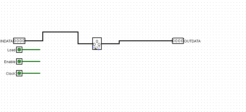
You are given a design board with four input pins a 4 - bit INDATA, 1 - bit Load,Enable, and Clock; and one output, a
You are given a design board with four input pins a bit INDATA,
bit Load,Enable, and Clock; and one output, a bit OUTDATA.
Build a sequential circuit that contains a register Dont forget to
trigger that register by the FALLING edge of the clock, Logisims default
is the opposite!
The register is updated every clock cycle in which Enable is up If
Load is down, the register is incremented, otherwise it is loaded with the
data asserted on the INDATA pin.
The register data output should be connected with the output pin
OUTDATA.
Use the Logisim template COMcircTLecirc attached
as a starting point for your circuit.
You may use any components you like from the Wiring, Gates, Plexers
and Arithmetic libraries, but the only components you may use from the
Memory library are registers.

Step by Step Solution
There are 3 Steps involved in it
Step: 1

Get Instant Access to Expert-Tailored Solutions
See step-by-step solutions with expert insights and AI powered tools for academic success
Step: 2

Step: 3

Ace Your Homework with AI
Get the answers you need in no time with our AI-driven, step-by-step assistance
Get Started


