Answered step by step
Verified Expert Solution
Question
1 Approved Answer
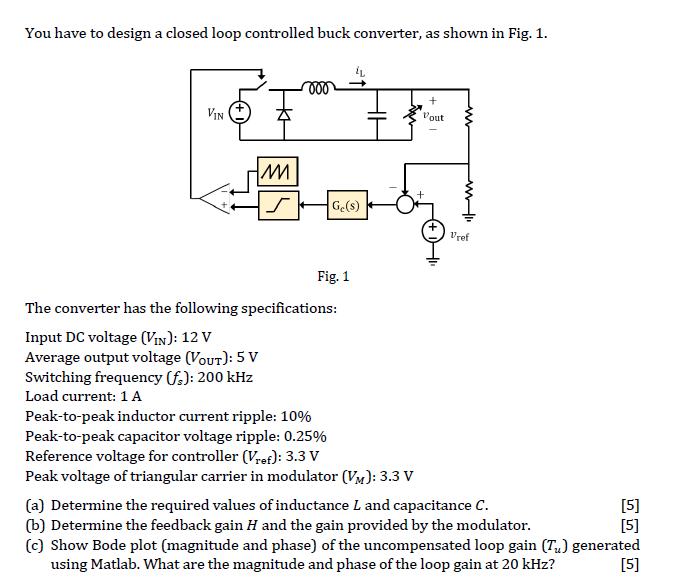
You have to design a closed loop controlled buck converter, as shown in Fig. 1. VIN IM S Ge(s) Fig. 1 The converter has

You have to design a closed loop controlled buck converter, as shown in Fig. 1. VIN IM S Ge(s) Fig. 1 The converter has the following specifications: Input DC voltage (VIN): 12 V Average output voltage (VOUT): 5 V Switching frequency (f): 200 kHz Load current: 1 A Peak-to-peak inductor current ripple: 10% Peak-to-peak capacitor voltage ripple: 0.25% Reference voltage for controller (Vref): 3.3 V Peak voltage of triangular carrier in modulator (VM): 3.3 V Vout Vref (a) Determine the required values of inductance L and capacitance C. (b) Determine the feedback gain H and the gain provided by the modulator. (c) Show Bode plot (magnitude and phase) of the uncompensated loop gain (Tu) generated using Matlab. What are the magnitude and phase of the loop gain at 20 kHz? [5] [5] [5]
Step by Step Solution
★★★★★
3.36 Rating (152 Votes )
There are 3 Steps involved in it
Step: 1
The image youve provided presents a design task for a closed loop controlled buck converter with specific requirements for performance Let me help you ...
Get Instant Access to Expert-Tailored Solutions
See step-by-step solutions with expert insights and AI powered tools for academic success
Step: 2

Step: 3

Ace Your Homework with AI
Get the answers you need in no time with our AI-driven, step-by-step assistance
Get Started


