

Question
Your organization is allocated a block of address 10.Y.0.0/23. You are required to plan the subnets and IP addressing based on the following address allocation
Your organization is allocated a block of address 10.Y.0.0/23.
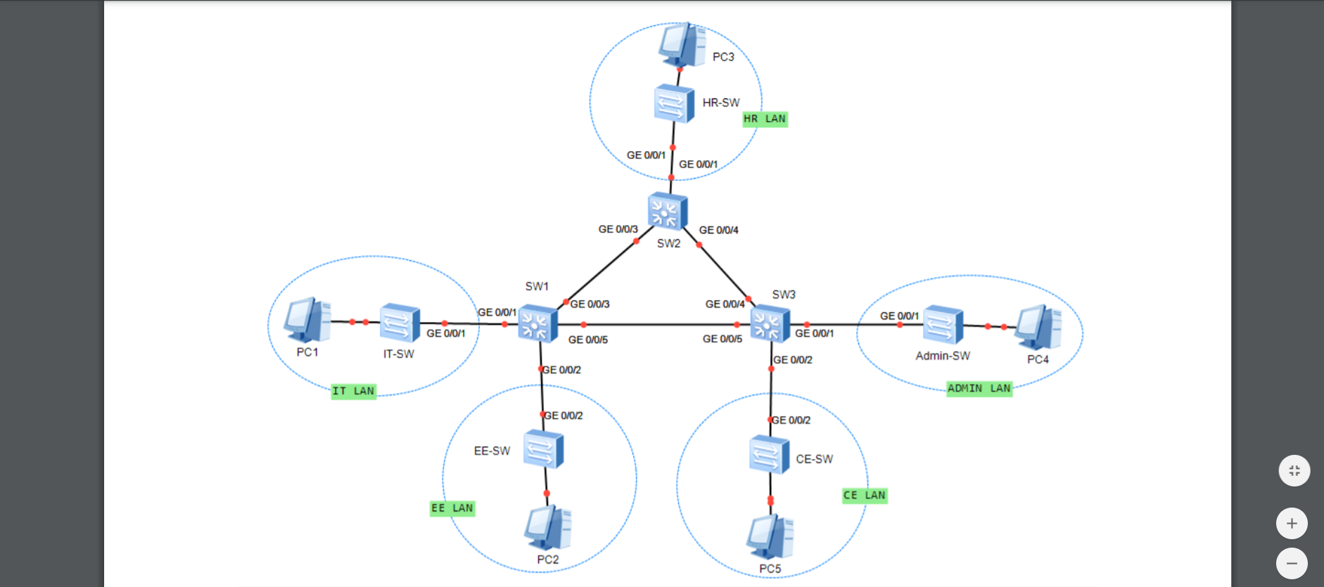
You are required to plan the subnets and IP addressing based on the following address allocation requirement for each subnet as shown in Figure 1.
The IT LAN requires i0 addresses
. The HR LAN requires j0 addresses.
The ADMIN LAN requires k0 addresses.
The CE LAN requires 10 addresses.
The EE LAN requires 30 addresses.
Each link segment between two Layer 3 switches requires 2 addresses.
Note:
Y will is 59.
i will be 7.
j denotes 5.
k denotes 9.
Task 1. Subnet Planning and Layer 3 Switch Configuration
1. Perform subnet planning for your organizations network. Show your work. 2. Assign VLAN ID and list the following address information for each subnet1 : Network address Usable IP address range Broadcast address Decimal / CIDR Subnet mask 3. Table 1 is used for your configuration plan. Fill in the IP address and subnet mask for each of the PC and VLANIFs interface. 4. Connect each device as shown in Figure 1. Select S5700 in eNSP as the Layer 3 switch for SW1, SW2, and SW3. (You can use S3700 if there is any issue of using S5700 with your eNSP) Use S3700 in eNSP for the remaining switches in the diagram. You can select any appropriate switchs interfaces for the link connection. Make sure you perform your configuration on the correct interfaces in the subsequent steps. Take a screenshot of your network topology. 5. Rename the three S5700 switches. You should configure it with your student ID followed by the device name as shown in Figure 1. For example, rename the switch SW1 as DMT1234567-SW1 if your student ID is DMT1234567. Take a screenshot of your configuration on switch SW1. A sample is shown in Figure 2. Figure 2 6. Configure the switches with VLANs and assign IP addresses to the interfaces based on the results that you have obtained in Table 1. Take screenshots of your configuration on switch SW1. Take screenshots of your configuration on switch SW2. Take screenshots of your configuration on switch SW3. 7. Configure the PCs based on the results that you have obtained in Table 1. Take screenshots of your configguration on PCs.
Q.2 : Dynamic Route Configuration 1. Disable STP on the interfaces connected between the three Layer 3 switches. For example, you can enter the following command to disable STP on interface GE 0/0/3 of SW1 as shown in Figure 3. Figure 3 2. Configure RIP version 2 on each switch. Take a screenshot of your configuration on switch SW1. Take a screenshot of your configuration on switch SW2. Take a screenshot of your configuration on switch SW3. 3. Verify the configuration by checking the routing table on each switch. Take a screenshot of the routing table on switch SW1. Take a screenshot of the routing table on switch SW2. Take a screenshot of the routing table on switch SW3. 4. Use the ping command to verify the connectivity between the PCs. Take screenshots of the ping results. 5. Enter the tracert command to trace the route from PC3 to PC4. Take a screenshot of the traceroute result.
Right-click the link between SW2 and SW3 and select Remove Connection. This will remove the link between SW2 and SW3
7. Enter the tracert command again to trace the route from PC3 to PC4.
PC3 HR-SW HR LAN GE 0/0/1 GE 0/0/1 GE 0/0/3 GE 0/0/4 SW2 SW1 SW3 GE 0/0/3 GE 0/0/4 GE 0/0/1 GE 0/0/1 GE 0/0/1 GE 0/0/1 GE 0/0/5 GE 0/0/5 PC1 IT-SW GE 0/0/2 Admin-SW PC4 GE 0/0/2 IT LAN ADMIN LAI GE 0/0/2 GE 0/0/2 EE-SW CE-SW CE LAN EE LAN + PC2 PC5 PC3 HR-SW HR LAN GE 0/0/1 GE 0/0/1 GE 0/0/3 GE 0/0/4 SW2 SW1 SW3 GE 0/0/3 GE 0/0/4 GE 0/0/1 GE 0/0/1 GE 0/0/1 GE 0/0/1 GE 0/0/5 GE 0/0/5 PC1 IT-SW GE 0/0/2 Admin-SW PC4 GE 0/0/2 IT LAN ADMIN LAI GE 0/0/2 GE 0/0/2 EE-SW CE-SW CE LAN EE LAN + PC2 PC5Step by Step Solution
There are 3 Steps involved in it
Step: 1

Get Instant Access to Expert-Tailored Solutions
See step-by-step solutions with expert insights and AI powered tools for academic success
Step: 2

Step: 3
Ace Your Homework with AI
Get the answers you need in no time with our AI-driven, step-by-step assistance
Get Started
Conceptual Database Design An Entity Relationship Approach
Authors: Carol Batini, Stefano Ceri, Shamkant B. Navathe
1st Edition
0805302441, 978-0805302448