

Question
Your task is to program the water supply buffer system for a process that requires a steady flow of water available for cooling. System Operation
Your task is to program the water supply buffer system for a process that requires a steady flow of water available for cooling.
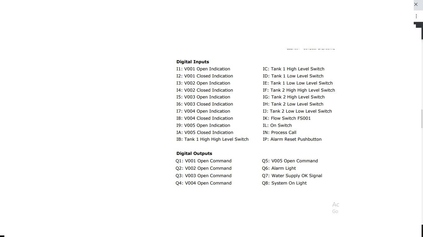
System Operation Refer to the provided Piping and Instrumentation Diagram to support this explanation. There are two tanks, TK001 and TK002. The two tanks work together to provide a steady flow of water for cooling to a separate process. There are two operations that may occur in a tank: fill and supply. When the system is first turned on, both tanks will fill. The system will then indicate to the following process that it is ready to supply water by activating the Water Supply OK output. When a Process Call input is received, tank 1 will supply the water to the process until the low level switch (LSL001) in tank 1 is activated. At this point, tank 2 will take over and supply water to the process while tank 1 fills until it reaches the high level switch (LSH001). This process continues, with one tank filling as the other supplies and then swapping over. The tanks are filled through valves V001 and V002. The tanks supply water through valves V003 and V004. V005 will be opened when either V003 or V004 are supplying water. The fill or supply functions will only operate when the On switch is activated. In addition, the supply function will only operate when the Process Call input is activated. Both tanks have high, high high, low and low low level sensors. The high and low level sensors should be used to swap between fill and supply functions. The high high and low low level sensors should be used to detect alarm conditions. All valves have position feedback and the program should include alarm logic. There is a flow switch after V005, which will alarm if there is no flow for 5 seconds when V005 is open. All inputs to be debounced for a suitable time. All alarms are to be latched. There is an alarm output to indicate alarm states, and an alarm reset pushbutton to clear alarms. There is another light which indicates when the system has been turned on
Step by Step Solution
There are 3 Steps involved in it
Step: 1

Get Instant Access to Expert-Tailored Solutions
See step-by-step solutions with expert insights and AI powered tools for academic success
Step: 2

Step: 3
Ace Your Homework with AI
Get the answers you need in no time with our AI-driven, step-by-step assistance
Get Started
Auditing Security And Controls Of Windows Active Directory Domains
Authors: Derek Melber
1st Edition
0894135635, 978-0894135637