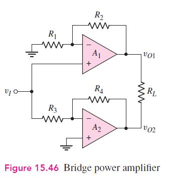
(a) Design the bridge circuit in Figure 15.46 such that the gain magnitude of each op-amp circuit...
Question:
(a) Design the bridge circuit in Figure 15.46 such that the gain magnitude of each op-amp circuit is 12.
(b) A load resistance of \(R_{L}=12 \Omega\) that is to dissipate an average power of \(\widehat{P_{L}}=15 \mathrm{~W}\) is connected to the output. Determine the peak output voltage at each op-amp and the peak current that each op-amp must source or sink.
(c) If the peak output voltage of each op-amp is limited to \(\pm 12 \mathrm{~V}\) and the peak current that each op-amp can source or sink is limited to \(0.8 \mathrm{~A}\), determine (i) the maximum average power that can be delivered to the load and (ii) the optimum value of load resistance.

Fantastic news! We've Found the answer you've been seeking!
Step by Step Answer:
Related Book For 

Microelectronics Circuit Analysis And Design
ISBN: 9780071289474
4th Edition
Authors: Donald A. Neamen
Question Posted:


