

Question: A low-power TTL logic gate with an active pnp pull-up device is shown in Figure P17.35. The transistor parameters are (beta_{F}=100) and (beta_{R}=0.2) (for each
A low-power TTL logic gate with an active pnp pull-up device is shown in Figure P17.35. The transistor parameters are \(\beta_{F}=100\) and \(\beta_{R}=0.2\) (for each input emitter). Assume a fanout of 5.
(a) For \(v_{X}=v_{Y}=v_{Z}=0.1 \mathrm{~V}\), determine \(i_{B 1}, i_{B 2}, i_{B 3}, i_{C 2}\), and \(i_{C 3}\).
(b) Repeat part (a) for \(v_{X}=v_{Y}=\) \(v_{Z}=2 \mathrm{~V}\).
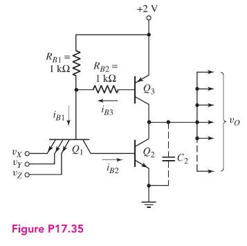
RB1 1 iB1. RB2= 1 www iB3 +2 V Q3 Vo vxo- Q2 Vy o 182 Figure P17.35
Step by Step Solution
★★★★★
3.45 Rating (161 Votes )
There are 3 Steps involved in it
1 Expert Approved Answer
Step: 1 Unlock

Question Has Been Solved by an Expert!
Get step-by-step solutions from verified subject matter experts
Step: 2 Unlock
Step: 3 Unlock