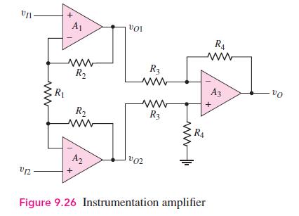
Assume the instrumentation amplifier in Figure 9.26 has ideal op-amps. The circuit parameters are (R_{1}=10 mathrm{k} Omega,
Question:
Assume the instrumentation amplifier in Figure 9.26 has ideal op-amps. The circuit parameters are \(R_{1}=10 \mathrm{k} \Omega, R_{2}=40 \mathrm{k} \Omega, R_{3}=40 \mathrm{k} \Omega\), and \(R_{4}=120 \mathrm{k} \Omega\). Determine \(v_{O 1}, v_{O 2}, v_{O}\), and the current in \(R_{1}\) for
(a) \(v_{I 2}=1.2+0.08 \sin \omega t(\mathrm{~V}), v_{I 1}=1.2-0.08 \sin \omega t(\mathrm{~V})\); and
(b) \(v_{I 2}=\) \(-0.60-0.05 \sin \omega t(\mathrm{~V}), v_{I 1}=-0.65+0.05 \sin \omega t(\mathrm{~V})\).
Figure 9.26:-

Fantastic news! We've Found the answer you've been seeking!
Step by Step Answer:
Related Book For 

Microelectronics Circuit Analysis And Design
ISBN: 9780071289474
4th Edition
Authors: Donald A. Neamen
Question Posted:


