

Question: Consider the summing amplifier in Figure 9.14 with (R_{F}=10 mathrm{k} Omega), (R_{1}=1 mathrm{k} Omega, R_{2}=5 mathrm{k} Omega), and (R_{3}=10 mathrm{k} Omega). If (v_{I 1}) is
Consider the summing amplifier in Figure 9.14 with \(R_{F}=10 \mathrm{k} \Omega\), \(R_{1}=1 \mathrm{k} \Omega, R_{2}=5 \mathrm{k} \Omega\), and \(R_{3}=10 \mathrm{k} \Omega\). If \(v_{I 1}\) is a \(1 \mathrm{kHz}\) sine wave with an rms value of \(50 \mathrm{mV}\), if \(v_{I 2}\) is a \(100 \mathrm{~Hz}\) square wave with an amplitude of \(\pm 1 \mathrm{~V}\), and if \(v_{I 3}=0\), sketch the output voltage \(v_{O}\).
Figure 9.14:-
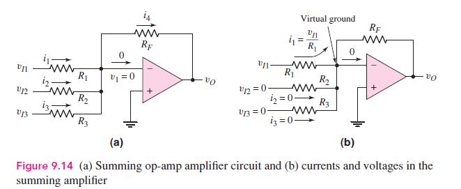
Virtual ground RF ww Un ww RF R ww R R v=0 VO R U12 12=0- R 2=0- R3 V13 V13=0 R3 i3=0 (a) (b) vo Figure 9.14 (a) Summing op-amp amplifier circuit and (b) currents and voltages in the summing amplifier
Step by Step Solution
3.42 Rating (161 Votes )
There are 3 Steps involved in it

Get step-by-step solutions from verified subject matter experts