

For the comparator in the circuit in Figure 15.26(a), the output saturation voltages are (pm 9 mathrm{~V}).
Question:
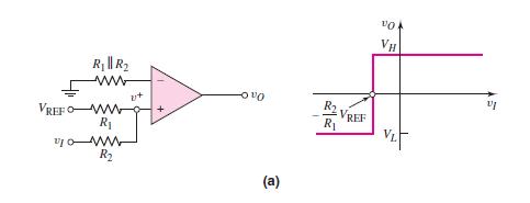
For the comparator in the circuit in Figure 15.26(a), the output saturation voltages are \(\pm 9 \mathrm{~V}\). Let \(V_{\text {REF }}=5 \mathrm{~V}\). Let \(R_{2}\) be a fixed resistor in series with a potentiometer. Design the circuit such that the crossover voltage can easily be varied over the range of \(-2 \mathrm{~V}\) to \(-4 \mathrm{~V}\). The minimum resistance is to be \(20 \mathrm{k} \Omega\).
Figure 15.26(a):-
Fantastic news! We've Found the answer you've been seeking!
Step by Step Answer:

Answered By
Sinmon Warui Kamau
After moving up and down looking for a job, a friend introduced me to freelance writing. I started with content writing and later navigated to academic writing. I love writing because apart from making a living out of it, it is also a method of learning and helping others to learn.
40+ Reviews
45+ Question Solved
Related Book For 

Microelectronics Circuit Analysis And Design
ISBN: 9780071289474
4th Edition
Authors: Donald A. Neamen
Question Posted:
